ESP8266 - Actuator
This tutorial instructs you how to use ESP8266 to control Linear Actuator. In detail, we will learn:
- How a linear actuator works
- How to program ESP8266 to make a linear actuator extend or retract
- How to program ESP8266 to control the speed of a linear actuator
There are two types of linear actuators:
- Linear actuators without feedback: They are typically used to move to the furthest point and cannot be controlled to stop at a specific position.
- Linear actuators with feedback: They can be controlled to move to a specific position because they have a feedback signal.
This tutorial is for linear actuator without feedback. If you are interested in learning about linear actuator with feedback, please refer to the ESP8266 - Actuator with Feedback tutorial.
Hardware Preparation
Or you can buy the following kits:
| 1 | × | DIYables Sensor Kit (18 sensors/displays) |
Additionally, some of these links are for products from our own brand, DIYables .
Overview of Linear Actuator

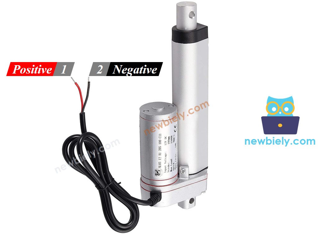
Linear Actuator Pinout
A Linear Actuator has two wires:
- The positive wire is usually red.
- The negative wire is usually black.
How It Works
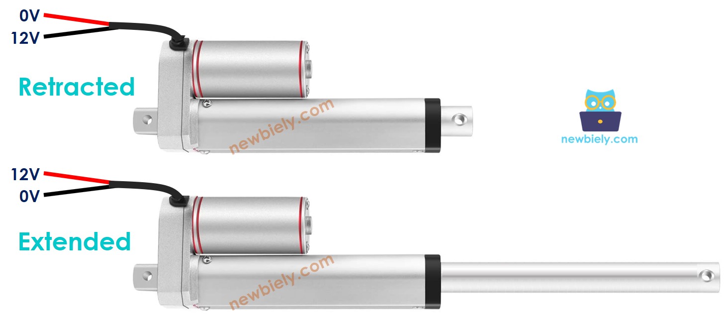
When purchasing a linear actuator, it is essential to be aware of the voltage that it requires to operate. For instance, let's consider a 12V linear actuator.
When you power the 12V linear actuator by a 12V power source:
- Connect 12V and GND to the positive wire and negative wire, respectively: the linear actuator will extend at full speed until it reaches the limit.
- Connect 12V and GND to the negative wire and positive wire, respectively: the linear actuator will retract at full speed until it reaches the limit.
If the power to the actuator is cut off, the extension or retraction process will cease.
※ NOTE THAT:
For DC motor, servo motor, and stepper motor without gearing, when a load is present, if power is cut, they will not maintain their position. In contrast, an actuator can retain its position even when power is removed while carrying a load.
If the voltage of the power supply for linear actuators is less than 12V, the linear actuator will still extend/retract, but not at its maximum speed. This means that changing the voltage of the power source can affect the speed of the linear actuator. However, this approach is not commonly used due to the difficulty in controlling the voltage of the power source. Therefore, the voltage of the power source is kept constant, and the speed of the linear actuator is regulated by a PWM signal. The higher the duty cycle of the PWM, the faster the linear actuator extends/retracts.
How to control a linear actuator using ESP8266
Managing a linear actuator involves:
- Extending the linear actuator at its maximum rate.
- Retracting the linear actuator at its maximum rate.
- (Optional) Adjusting the speed of extending and retracting.
ESP8266 is able to generate a signal that can be used to control a linear actuator, however, the voltage and current of this signal is too low to be used as is. Therefore, a hardware driver must be used to bridge the gap between ESP8266 and the linear actuator. The driver has two functions:
- Amplify the control signal from ESP8266 (regarding both voltage and current)
- Receive another control signal from ESP8266 to switch the polarity of the power supply, thus allowing for direction control.
※ NOTE THAT:
- This tutorial can be used for all linear actuators, with 12V linear actuator being just an example.
- When controlling a 5V linear actuator, even though the ESP8266 pin outputs 5V (which is the same voltage as the linear actuator), you still need a driver between the ESP8266 and linear actuator because the ESP8266 pin does not provide enough current for the linear actuator.
There are numerous types of chips and module available for linear actuator drivers. For this tutorial, we will be using the L298N driver.
Overview of L298N Driver
The L298N Driver can be used to control linear actuator, DC motor and stepper motor. This tutorial instructs you how to use it to regulate the linear actuator.
L298N Driver Pinout
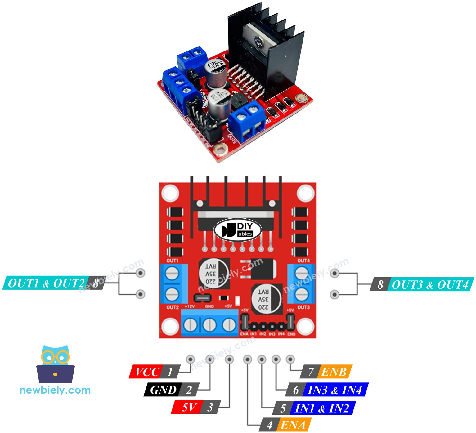
The L298N Driver has two channels, labeled A and B. This means it can independently control two linear actuators at the same time. Suppose linear actuator A is connected to channel A and linear actuator B is connected to channel B. The L298N Driver has thirteen pins.
The common pins for both channels:
- VCC pin: This pin provides power to the linear actuator and can range from 5 to 35V.
- GND pin: This is a ground pin that must be connected to 0V (GND).
- 5V pin: This pin supplies power to the L298N module and can be sourced from the 5V output of an ESP8266.
Channel A pins:
- ENA pins: These pins are used to control the speed of linear actuator A. By removing the jumper and connecting this pin to PWM input, we can control the speed at which the linear actuator extends and retracts.
- IN1 & IN2 pins: These pins are used to control the direction of a linear actuator. When one of them is set to HIGH and the other to LOW, the linear actuator will either extend or retract. If both inputs are either HIGH or LOW, the linear actuator will stop.
- OUT1 & OUT2 pins: These pins are connected to linear actuator A.
Channel B pins:
- ENB pins: are used to regulate the speed of linear actuator B. Taking out the jumper and connecting this pin to PWM input will enable us to control the extending/retracting speed of linear actuator B.
- IN3 & IN4 pins: are utilized to control the moving direction of a linear actuator. When one of them is HIGH and the other is LOW, the a linear actuator will extend or retract. If both the inputs are either HIGH or LOW the linear actuator will cease.
- OUT3 & OUT4 pins: are connected to a linear actuator.
The L298N driver has two input powers:
- One for the linear actuator with a voltage range of 5 to 35V, connected to the VCC and GND pins.
- One for the internal operation of the L298N module, with a voltage range of 5 to 7V, connected to the 5V and GND pins.
Remove all jumpers from the L298N driver for simplicity.
We can manage two linear actuators independently simultaneously with the help of an ESP8266 and an L298N Driver. Just three pins from ESP8266 are required to control each linear actuator.
※ NOTE THAT:
The remainder of this tutorial will focus on controlling a linear actuator via Channel A. The process for controlling the other linear actuator is similar.
How To Control Linear Actuator
We will be studying the technique of managing a Linear Actuator with the help of an L298N driver.
Wiring Diagram
Take off all three jumpers on the L298N module before connecting it.

This image is created using Fritzing. Click to enlarge image
See more in ESP8266's pinout and how to supply power to the ESP8266 and other components.
How To Make Linear Actuator Expand/Retract
The Linear Actuator's moving direction can be managed by giving either a logic HIGH or LOW to IN1 and IN2 pins. The table below shows how to manage the direction in both channels.
| IN1 pin | IN2 pin | Direction |
|---|---|---|
| LOW | LOW | Linear Actuator A stops |
| HIGH | HIGH | Linear Actuator A stops |
| HIGH | LOW | Linear Actuator A extends |
| LOW | HIGH | Linear Actuator A retracts |
- Extends Linear Actuator A.
- Retracts the Linear Actuator A
※ NOTE THAT:
The orientation of the linear actuator can be changed by connecting the OUT1 & OUT2 pin in a different order. To do this, it is necessary to either switch the OUT1 & OUT2 pin or alter the control signal on IN1 and IN2 pin in the code.
How To Stop Linear Actuator from Extending or Retracting
The linear actuator will cease extending/retracting when it reaches the limit. Additionally, we can program it to stop extending/retracting before it reaches the limit.
There are two methods to halt a linear actuator:
- Reduce the speed to 0
- Disconnect the power source
- Sets the IN1 and IN2 pins to the same value, either LOW or HIGH.
- Or
How To Control the Speed of Linear Actuator via L298N Driver
It is easy to regulate the speed of the linear actuator. Instead of setting the ENA pin to HIGH, we can produce a PWM signal to the ENA pin. This can be done by:
- Connecting an ESP8266 pin to the ENA of the L298N
- Generating a PWM signal to the ENA pin by using analogWrite() function. The L298N Driver amplifies the PWM signal to the linear actuator.
The speed is a value ranging from 0 to 255. When the speed is 0, the linear actuator will come to a halt. At a speed of 255, the linear actuator will extend/retract at its maximum velocity.
ESP8266 Example Code
The code below:
- Increases the linear actuator to its maximum speed
- Halts the linear actuator
- Decreases the linear actuator to its maximum speed
- Halts the linear actuator again
Detailed Instructions
To get started with ESP8266 on Arduino IDE, follow these steps:
- Check out the how to setup environment for ESP8266 on Arduino IDE tutorial if this is your first time using ESP8266.
- Wire the components as shown in the diagram.
- Connect the ESP8266 board to your computer using a USB cable.
- Open Arduino IDE on your computer.
- Choose the correct ESP8266 board, such as (e.g. NodeMCU 1.0 (ESP-12E Module)), and its respective COM port.
Take out all three jumpers from the L298N module.
Copy the code above and open it in the Arduino IDE.
Click the Upload button on the Arduino IDE to upload the code to the ESP8266.
You will observe:
- The linear actuator will extend until it reaches the limit, then it will stop.
- The linear actuator will remain in that position for a certain amount of time.
- The linear actuator will retract until it reaches the limit, then it will stop.
- The linear actuator will stay in that position for a certain amount of time.
- This process will be repeated continuously.