ESP8266 - Heating Element
This tutorial instructs you how to ESP8266 to control a heating element. Subsequently, you will be able to apply this knowledge to create a heating system in a different tutorial.
Hardware Preparation
Or you can buy the following kits:
| 1 | × | DIYables Sensor Kit (18 sensors/displays) |
Additionally, some of these links are for products from our own brand, DIYables .
Overview of Heating Element
The Heating Element Pinout
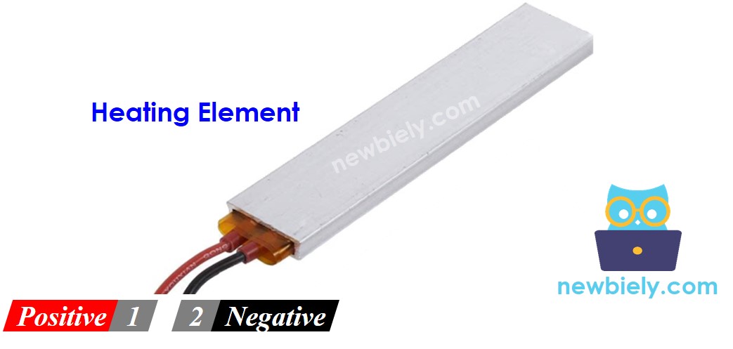
The heating element typically has two pins:
- The Positive (+) pin (red) should be connected to the 12V of the DC power supply
- The Negative (-) pin (black) should be connected to the GND of the DC power supply
How to Control Heating Element using ESP8266
If a 12V heating element is powered by a 12V power supply, it will emit heat. In order to control the heating element, a relay must be used between the ESP8266 and the heating element. The ESP8266 can then control the heating element through the relay.
If you are not familiar with relays (pinout, how it works, how to program, etc.), please refer to the ESP8266 - Relay tutorial for more information.
Wiring Diagram
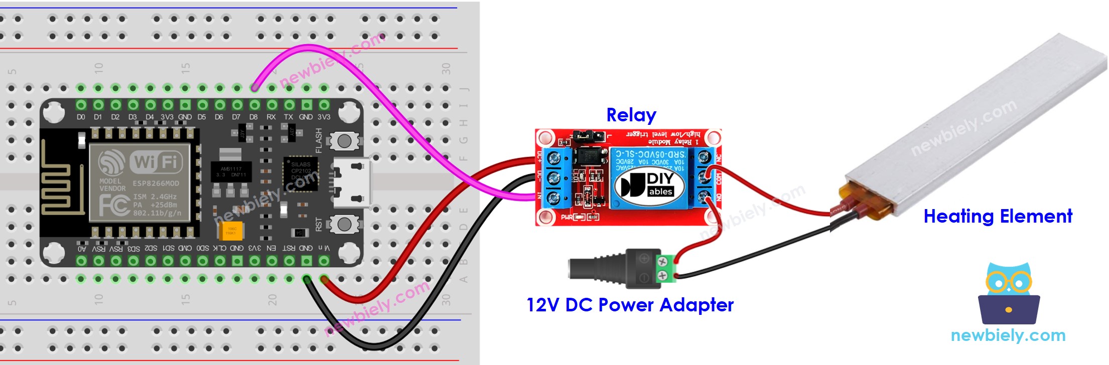
This image is created using Fritzing. Click to enlarge image
See more in ESP8266's pinout and how to supply power to the ESP8266 and other components.
ESP8266 Code
The code below will turn the heating element ON every five seconds and OFF every five seconds, . repeatedly.
Detailed Instructions
To get started with ESP8266 on Arduino IDE, follow these steps:
- Check out the how to setup environment for ESP8266 on Arduino IDE tutorial if this is your first time using ESP8266.
- Wire the components as shown in the diagram.
- Connect the ESP8266 board to your computer using a USB cable.
- Open Arduino IDE on your computer.
- Choose the correct ESP8266 board, such as (e.g. NodeMCU 1.0 (ESP-12E Module)), and its respective COM port.
- Plug the USB cable into the ESP8266 and your computer.
- Launch the Arduino IDE, select the appropriate board and port.
- Paste the code into the Arduino IDE.
- Click the Upload button in the Arduino IDE to send the code to the ESP8266.
- Check out the temperature of the heating element.
WARNING
Take caution. It can cause harm to you and your home. This is an important matter and we want you to be secure. If you are not completely certain of what you are doing, it is best to not meddle with anything. Consult someone who is knowledgeable! We cannot be held responsible for your safety.
Code Explanation
Check out the line-by-line explanation contained in the comments of the source code!