ESP8266 - Ultrasonic Sensor - Piezo Buzzer
This tutorial instructs you how to use ESP8266 and ultrasonic sensor to control piezo buzzer. In detail:
- ESP8266 produces a sound when the object is near the ultrasonic sensor.
- ESP8266 ceases the sound when the object is far from the ultrasonic sensor.
- ESP8266 play a melody of a song when the object is close to the ultrasonic sensor.
Hardware Preparation
Or you can buy the following kits:
| 1 | × | DIYables Sensor Kit (18 sensors/displays) |
Disclosure: Some of the links provided in this section are Amazon affiliate links. We may receive a commission for any purchases made through these links at no additional cost to you.
Additionally, some of these links are for products from our own brand, DIYables .
Additionally, some of these links are for products from our own brand, DIYables .
Overview of Piezo Buzzer and Ultrasonic Sensor
If you are unfamiliar with piezo buzzer and ultrasonic sensor (including pinout, functioning, programming, etc.), the following tutorials can help:
Wiring Diagram
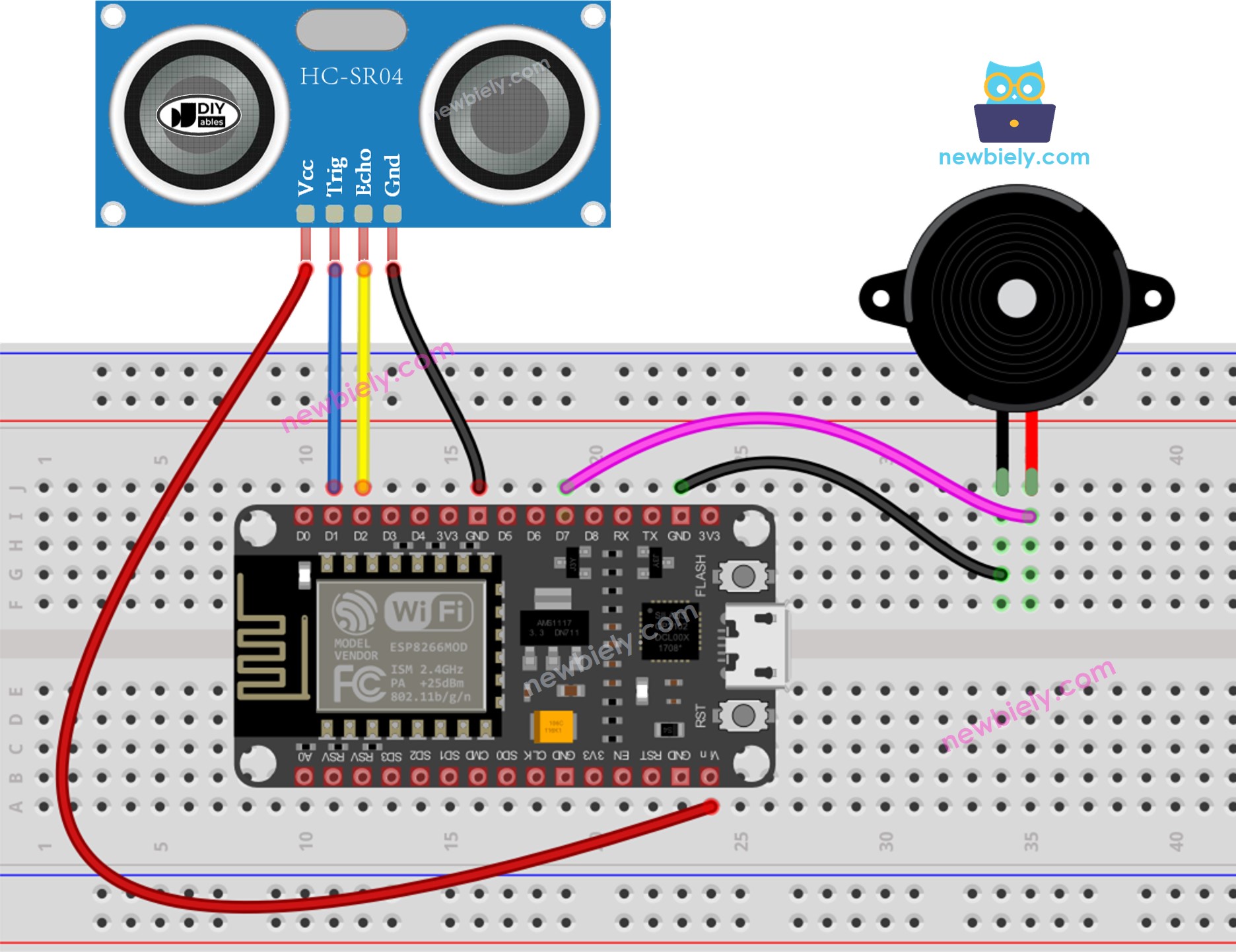
This image is created using Fritzing. Click to enlarge image
See more in ESP8266's pinout and how to supply power to the ESP8266 and other components.
ESP8266 Code - Simple Sound
/*
* This ESP8266 NodeMCU code was developed by newbiely.com
*
* This ESP8266 NodeMCU code is made available for public use without any restriction
*
* For comprehensive instructions and wiring diagrams, please visit:
* https://newbiely.com/tutorials/esp8266/esp8266-ultrasonic-sensor-piezo-buzzer
*/
#define TRIG_PIN D1 // The ESP8266 pin D1 connected to Ultrasonic Sensor's TRIG pin
#define ECHO_PIN D2 // The ESP8266 pin D2 connected to Ultrasonic Sensor's ECHO pin
#define BUZZER_PIN D7 // The ESP8266 pin D7 connected to Piezo Buzzer's pin
#define DISTANCE_THRESHOLD 50 // centimeters
float duration_us, distance_cm;
void setup() {
Serial.begin (9600); // Initialize the Serial to communicate with the Serial Monitor.
pinMode(TRIG_PIN, OUTPUT); // Configure the ESP8266 pin to the output mode
pinMode(ECHO_PIN, INPUT); // Configure the ESP8266 pin to the input mode
pinMode(BUZZER_PIN, OUTPUT); // Configure the ESP8266 pin to the output mode
}
void loop() {
// Produce a 10-microsecond pulse to the TRIG pin.
digitalWrite(TRIG_PIN, HIGH);
delayMicroseconds(10);
digitalWrite(TRIG_PIN, LOW);
// Measure the pulse duration from the ECHO pin
duration_us = pulseIn(ECHO_PIN, HIGH);
// calculate the distance
distance_cm = 0.017 * duration_us;
if (distance_cm < DISTANCE_THRESHOLD)
digitalWrite(BUZZER_PIN, HIGH); // turn on Piezo Buzzer
else
digitalWrite(BUZZER_PIN, LOW); // turn off Piezo Buzzer
// print the value to Serial Monitor
Serial.print("distance: ");
Serial.print(distance_cm);
Serial.println(" cm");
delay(500);
}
Detailed Instructions
To get started with ESP8266 on Arduino IDE, follow these steps:
- Check out the how to setup environment for ESP8266 on Arduino IDE tutorial if this is your first time using ESP8266.
- Wire the components as shown in the diagram.
- Connect the ESP8266 board to your computer using a USB cable.
- Open Arduino IDE on your computer.
- Choose the correct ESP8266 board, such as (e.g. NodeMCU 1.0 (ESP-12E Module)), and its respective COM port.
- Connect your ESP8266 to your computer using a USB cable.
- Launch the Arduino IDE and select the appropriate board and port.
- Copy the code provided and open it in the Arduino IDE.
- Click the Upload button in the Arduino IDE to compile and upload the code to the ESP8266.
- Wave your hand in front of the sensor.
- Listen to the sound coming from the piezo buzzer.
Code Explanation
Check out the line-by-line explanation contained in the comments of the source code!
ESP8266 Code - Melody
/*
* This ESP8266 NodeMCU code was developed by newbiely.com
*
* This ESP8266 NodeMCU code is made available for public use without any restriction
*
* For comprehensive instructions and wiring diagrams, please visit:
* https://newbiely.com/tutorials/esp8266/esp8266-ultrasonic-sensor-piezo-buzzer
*/
#include "pitches.h"
#define TRIG_PIN D1 // The ESP8266 pin D1 connected to Ultrasonic Sensor's TRIG pin
#define ECHO_PIN D2 // The ESP8266 pin D2 connected to Ultrasonic Sensor's ECHO pin
#define BUZZER_PIN D7 // The ESP8266 pin D7 connected to Piezo Buzzer's pin
#define DISTANCE_THRESHOLD 50 // centimeters
float duration_us, distance_cm;
// notes in the melody:
int melody[] = {
NOTE_E5, NOTE_E5, NOTE_E5,
NOTE_E5, NOTE_E5, NOTE_E5,
NOTE_E5, NOTE_G5, NOTE_C5, NOTE_D5,
NOTE_E5,
NOTE_F5, NOTE_F5, NOTE_F5, NOTE_F5,
NOTE_F5, NOTE_E5, NOTE_E5, NOTE_E5, NOTE_E5,
NOTE_E5, NOTE_D5, NOTE_D5, NOTE_E5,
NOTE_D5, NOTE_G5
};
// note durations: 4 = quarter note, 8 = eighth note, etc, also called tempo:
int noteDurations[] = {
8, 8, 4,
8, 8, 4,
8, 8, 8, 8,
2,
8, 8, 8, 8,
8, 8, 8, 16, 16,
8, 8, 8, 8,
4, 4
};
void setup() {
pinMode(TRIG_PIN, OUTPUT); // Configure the ESP8266 pin to the output mode
pinMode(ECHO_PIN, INPUT); // Configure the ESP8266 pin to the input mode
}
void loop() {
// Produce a 10-microsecond pulse to the TRIG pin.
digitalWrite(TRIG_PIN, HIGH);
delayMicroseconds(10);
digitalWrite(TRIG_PIN, LOW);
// Measure the pulse duration from the ECHO pin
duration_us = pulseIn(ECHO_PIN, HIGH);
// calculate the distance
distance_cm = 0.017 * duration_us;
if (distance_cm < DISTANCE_THRESHOLD)
buzzer(); // play a song
delay(500);
}
void buzzer() {
// iterate over the notes of the melody:
int size = sizeof(noteDurations) / sizeof(int);
for (int thisNote = 0; thisNote < size; thisNote++) {
// to calculate the note duration, take one second divided by the note type.
//e.g. quarter note = 1000 / 4, eighth note = 1000/8, etc.
int noteDuration = 1000 / noteDurations[thisNote];
tone(BUZZER_PIN, melody[thisNote], noteDuration);
// to distinguish the notes, set a minimum time between them.
// The note's duration + 30% seems to work well:
int pauseBetweenNotes = noteDuration * 1.30;
delay(pauseBetweenNotes);
// stop the tone playing:
noTone(BUZZER_PIN);
}
}
Detailed Instructions
- Wire the components as shown in the diagram.
- Connect the ESP8266 board to your computer using a USB cable.
- Open Arduino IDE on your computer.
- Choose the correct ESP8266 board, such as (e.g. NodeMCU 1.0 (ESP-12E Module)), and its respective COM port.
- Copy the code and open it with the Arduino IDE.
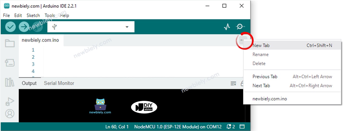
- Create the pitches.h file On Arduino IDE by:
- Either click on the button just below the serial monitor icon and choose New Tab, or use Ctrl+Shift+N keys.
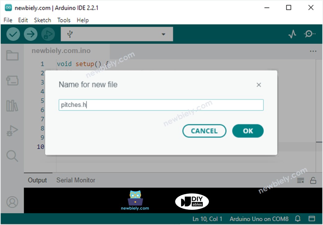
- Give file's name pitches.h and click OK button
- Copy the below code and paste it to the created pitches.h file.
- Click the Upload button on the Arduino IDE to send the code to the ESP8266.
- Move your hand in front of the sensor.
- Hear the tune that the piezo buzzer is playing.
- This code is intended for learning purposes. The ultrasonic sensor is very sensitive to noise. If you want to use it in practice, you should filter noise for the ultrasonic sensor. See how to filter noise for ultrasonic sensor for more information.
/*************************************************
* Public Constants
*************************************************/
#define NOTE_B0 31
#define NOTE_C1 33
#define NOTE_CS1 35
#define NOTE_D1 37
#define NOTE_DS1 39
#define NOTE_E1 41
#define NOTE_F1 44
#define NOTE_FS1 46
#define NOTE_G1 49
#define NOTE_GS1 52
#define NOTE_A1 55
#define NOTE_AS1 58
#define NOTE_B1 62
#define NOTE_C2 65
#define NOTE_CS2 69
#define NOTE_D2 73
#define NOTE_DS2 78
#define NOTE_E2 82
#define NOTE_F2 87
#define NOTE_FS2 93
#define NOTE_G2 98
#define NOTE_GS2 104
#define NOTE_A2 110
#define NOTE_AS2 117
#define NOTE_B2 123
#define NOTE_C3 131
#define NOTE_CS3 139
#define NOTE_D3 147
#define NOTE_DS3 156
#define NOTE_E3 165
#define NOTE_F3 175
#define NOTE_FS3 185
#define NOTE_G3 196
#define NOTE_GS3 208
#define NOTE_A3 220
#define NOTE_AS3 233
#define NOTE_B3 247
#define NOTE_C4 262
#define NOTE_CS4 277
#define NOTE_D4 294
#define NOTE_DS4 311
#define NOTE_E4 330
#define NOTE_F4 349
#define NOTE_FS4 370
#define NOTE_G4 392
#define NOTE_GS4 415
#define NOTE_A4 440
#define NOTE_AS4 466
#define NOTE_B4 494
#define NOTE_C5 523
#define NOTE_CS5 554
#define NOTE_D5 587
#define NOTE_DS5 622
#define NOTE_E5 659
#define NOTE_F5 698
#define NOTE_FS5 740
#define NOTE_G5 784
#define NOTE_GS5 831
#define NOTE_A5 880
#define NOTE_AS5 932
#define NOTE_B5 988
#define NOTE_C6 1047
#define NOTE_CS6 1109
#define NOTE_D6 1175
#define NOTE_DS6 1245
#define NOTE_E6 1319
#define NOTE_F6 1397
#define NOTE_FS6 1480
#define NOTE_G6 1568
#define NOTE_GS6 1661
#define NOTE_A6 1760
#define NOTE_AS6 1865
#define NOTE_B6 1976
#define NOTE_C7 2093
#define NOTE_CS7 2217
#define NOTE_D7 2349
#define NOTE_DS7 2489
#define NOTE_E7 2637
#define NOTE_F7 2794
#define NOTE_FS7 2960
#define NOTE_G7 3136
#define NOTE_GS7 3322
#define NOTE_A7 3520
#define NOTE_AS7 3729
#define NOTE_B7 3951
#define NOTE_C8 4186
#define NOTE_CS8 4435
#define NOTE_D8 4699
#define NOTE_DS8 4978
Code Explanation
Check out the line-by-line explanation contained in the comments of the source code!
※ NOTE THAT: