ESP8266 - WS2812B LED Strip
The WS2812B RGB LED strip is composed of LEDs whose color and brightness can be adjusted individually. This tutorial instructs you how to use ESP8266 to control the WS2812B RGB LED strip. In detail, we will learn:
- How to connect the WS2812B LED strip to ESP8266
- How to program ESP8266 to control the color of each individual LED on the WS2812B LED strip.
- How to program ESP8266 to control the brightness of each individual LED on the WS2812B LED strip.
We only need to use one ESP8266's digital pin to control all the LEDs on the strip.
Hardware Preparation
Or you can buy the following kits:
| 1 | × | DIYables Sensor Kit (18 sensors/displays) |
Additionally, some of these links are for products from our own brand, DIYables .
Overview of WS2812B RGB LED Strip
The WS2812B LED Strip Pinout
The WS2812B RGB LED Strip has three pins that require specific connections:
- GND pin must be linked to GND (0V)
- VCC pin should be connected to the 5V of an external power source
- Din pin is the pin that receives the control signal and should be linked to an ESP8266 pin.
※ NOTE THAT:
The sequence of pins may differ depending on the manufacturer. It is IMPERATIVE to use the markings printed on the LED Strip.
Wiring Diagram
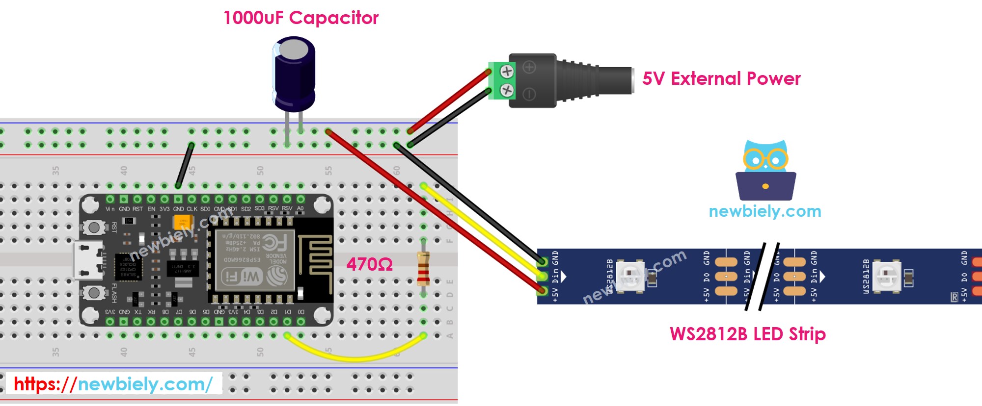
This image is created using Fritzing. Click to enlarge image
See more in ESP8266's pinout and how to supply power to the ESP8266 and other components.
How To Program For WS2812B RGB LED Strip
There are two libraries can be used to control WS2812B led strip:
- Adafruit NeoPixel library.
- FastLED library.
This tutorial will use the Adafruit NeoPixel library.
- Create a WS2812B object
- Strip with 30 LEDs
- Initiates the WS2812B strip which contains 30 lights.
- Specify the colour of each LED (known as a pixel).
- Adjust the brightness of all the strips.
※ NOTE THAT:
- WS2812B.setBrightness() is used to adjust the brightness of all pixels on the LED strip. To set the brightness for each individual pixel, we can scale the color values (R,G, B) with the same ratio.
- The values set by WS2812B.setBrightness() and WS2812B.setPixelColor() will only be applied when WS2812B.show() is executed.
ESP8266 Code
The code below does the following sequences:
- Turn pixels to green one-by-one with a delay between each pixel
- Turns off all pixels for two seconds
- Lights up all pixels red simultaneously for two seconds
- Repeats this process endlessly
Detailed Instructions
To get started with ESP8266 on Arduino IDE, follow these steps:
- Check out the how to setup environment for ESP8266 on Arduino IDE tutorial if this is your first time using ESP8266.
- Wire the components as shown in the diagram.
- Connect the ESP8266 board to your computer using a USB cable.
- Open Arduino IDE on your computer.
- Choose the correct ESP8266 board, such as (e.g. NodeMCU 1.0 (ESP-12E Module)), and its respective COM port.
- Click to the Libraries icon on the left bar of the Arduino IDE.
- Search for “Adafruit NeoPixel” and locate the NeoPixel library from Adafruit.
- Then, press the Install button to install the NeoPixel library.
- Copy the code and open it in the Arduino IDE.
- Click the Upload button to send the code to the ESP8266.
- Check out the LED effect.
※ NOTE THAT:
For any intricate LED effect, we provide the paid programming service