ESP8266 - RFID Door Lock
This tutorial instructs you how to build a door lock system using ESP8266, RFID/NFC RC522 module, a relay, solenoid lock or electromagnetic lock, and optionally LCD. To make it easy for you, the tutorial instructs you to build the RFID door lock from simple to complex steps. In detail, we will do:
- Part 1: A simple RFID door lock system with ESP8266, keypad, solenoid lock or electromagnetic lock, supports a single RFID key
- Part 2: (Optionally) Adding multiple RFID keys supports
- Part 3: (Optionally) Adding LCD display to the RFID door lock.
- Part 4: (Optionally) Adding a door sensor to the RFID door lock.
- Part 5: (Optionally) Managing and storing the valid RFID keys to ESP8266's internal EEPROM
- Part 6: (Optionally) Storing the access history to SD Card
If you want to build door lock system using password, please refer to ESP8266 - Keypad Door Lock.
Hardware Preparation
Or you can buy the following kits:
| 1 | × | DIYables Sensor Kit (18 sensors/displays) |
Additionally, some of these links are for products from our own brand, DIYables .
Overview of RFID/NFC RC522 Module and Electromagnetic Lock
If you are unfamiliar with the RFID/NFC RC522 Module, electromagnetic lock, solenoid lock (including pinout, how it works, and how to program), then you can learn more by following these tutorials:
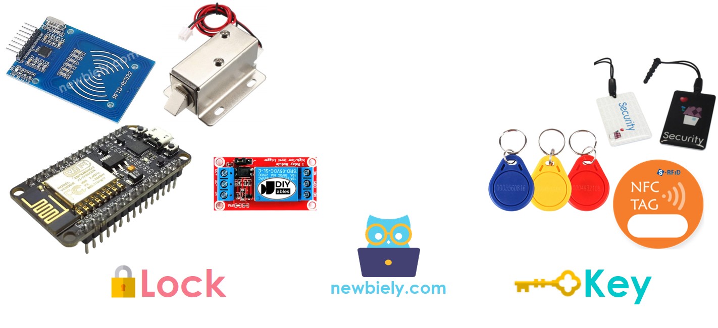
Door Lock System Components
The door lock system comprises two primary components:
- Door Lock: an ESP8266, a relay, a RFID/NFC reader, a solenoid lock or an electromagnetic lock
- Door Key: RFID/NFC tags
How RFID/NFC Door Lock Works
- The user taps an RFID/NFC tag on the RFID/NFC reader, which reads the UID from the tag.
- ESP8266 then gets the UID from the reader and compares it with the UIDs that have been set in the code.
- If the UID matches one of the predefined UIDs, ESP8266 will deactivate the solenoid lock, thus unlocking the door.
- These tags act as the authorized keys.
- The relay will be activated by ESP8266 to lock the door after a specific period of time.
Wiring Diagram
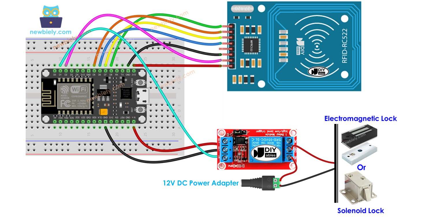
- RFID RC522 Door Lock with Solenoid Lock
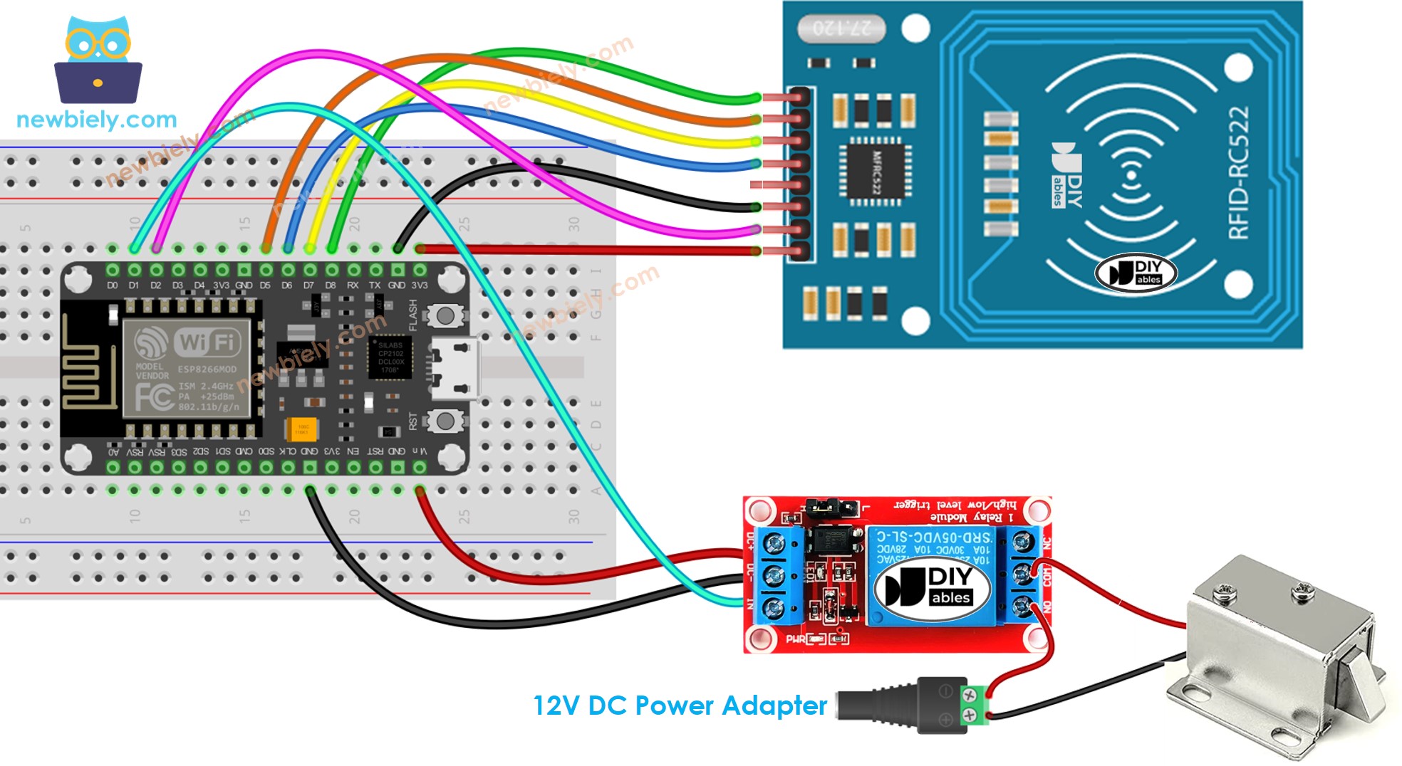
This image is created using Fritzing. Click to enlarge image
- RFID RC522 Door Lock with Electromagnetic Lock
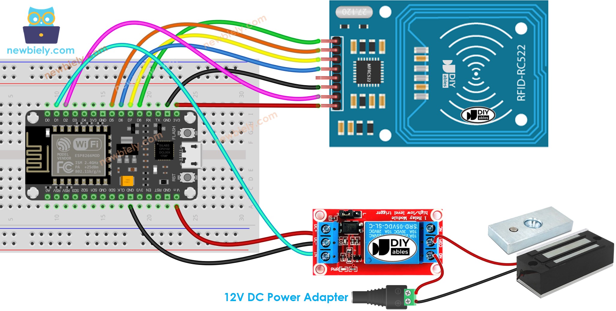
This image is created using Fritzing. Click to enlarge image
※ NOTE THAT:
Manufacturers may arrange the order of pins differently, so it is important to rely on the labels printed on the module. The pinout diagram depicted above displays the pin arrangement for modules produced by the manufacturer DIYables.
ESP8266 Code - Single Key
Detailed Instructions
To get started with ESP8266 on Arduino IDE, follow these steps:
- Check out the how to setup environment for ESP8266 on Arduino IDE tutorial if this is your first time using ESP8266.
- Wire the components as shown in the diagram.
- Connect the ESP8266 board to your computer using a USB cable.
- Open Arduino IDE on your computer.
- Choose the correct ESP8266 board, such as (e.g. NodeMCU 1.0 (ESP-12E Module)), and its respective COM port.
In order to determine the UID of an RFID/NFC tag:
- Upload code to ESP8266 and open Serial Monitor.
- Tap the tag on the RFID-RC522 module and the UID will be displayed on the Serial Monitor.
Once you have the UID:
- Alter line 18 of the code above to reflect the UID. For example, replace byte keytagUID[4] = {0xFF, 0xFF, 0xFF, 0xFF}; with byte keytagUID[4] = {0x3A, 0xC9, 0x6A, 0xCB};
- Upload the modified code to the ESP8266
- Place an RFID/NFC tag on the RFID-RC522 module
- Check the output on the Serial Monitor
- Verify that the electromagnetic lock is not locked.
- Tap a different RFID/NFC tag on the RFID-RC522 module.
- Check out the output on the Serial Monitor.
※ NOTE THAT:
- To facilitate testing, the unlocked time has been set to 2 seconds; however, it should be increased for practical use/demonstration.
- Installation of the MFRC522 library is necessary. For more information, please refer to the ESP8266 - RFID/NFC RC522 tutorial.
ESP8266 Code - Multiple Keys
Let us envision a room in which only the manager and secretary can gain access.
In this instance, two RFID/NFC tags are required: one for the manager and the other for the secretary. The UIDs of the two tags must be specified in the code.
Repeat the same steps as before, and then tap each tag on the RFID-RC522 module. The output on the Serial Monitor should appear as follows:
You can expand the code written above to include three, four, or more tags.
Adding LCD Display to the RFID Door Lock
We can optionally add a LCD display to show the access status (e.g. GRANTED/DENIED) to users. You can learn more about LCD in ESP8266 - LCD tutorial
Wiring diagram - Door lock system using RFID, solenoid lock or electromagnetic lock, and LCD display
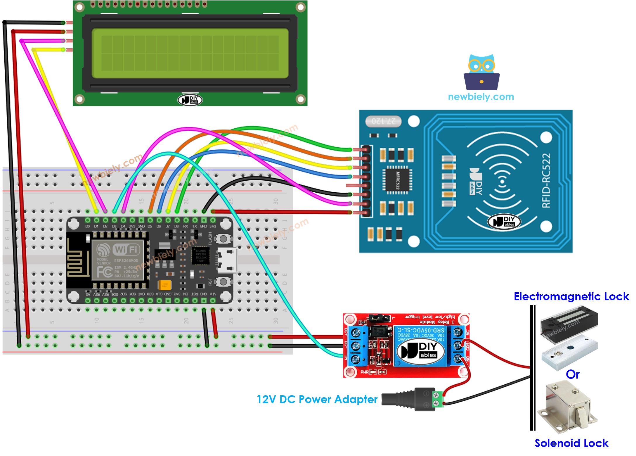
This image is created using Fritzing. Click to enlarge image
See more in ESP8266's pinout and how to supply power to the ESP8266 and other components.
Please note that in the wiring diagram above, 5V power is added because the 5V pin of the ESP8266 cannot supply enough power for both the relay and LCD simultaneously.
ESP8266 Code - Door lock system with password using RFID RC522 module, solenoid lock or electromagnetic lock, and LCD display
※ NOTE THAT:
The address of the LCD can differ depending on the manufacturer. We used 0x27 in our code, as specified by DIYables.
Adding a door sensor to the RFID door lock
In the previously mentioned code, the ESP8266 locks the door after a timeout since unlocking. However, in practical applications, a door sensor is usually added to the system. If the ESP8266 detects that the door is closed, it locks the door immediately instead of waiting for the timeout.
To avoid overwhelming you, we didn't include the door sensor in the wiring diagram and code. Instead, we're leaving this part up to your creativity. You can check out the ESP8266 - Door Sensor and ESP8266 - Door Sensor control Relay tutorials for more guidance.
Managing and storing the valid RFID keys to EEPROM
The above code has valid RFID keys (UID) that are hardcoded into the ESP8266 code. This means that if you want to add or remove keys, you have to make changes to the code and upload it to the ESP8266 again, which is inconvenient.
In real-life applications, it's necessary to manage RFID keys without having to modify and upload the code every time. To achieve this, the RFID keys can be stored in EEPROM instead of being hardcoded. Consequently, a method is needed to easily manage the RFID keys from the EEPROM.
Two methods are available for managing RFID keys in EEPROM:
- RFID keys as master keys
- By utilizing a RFID key as an ADD master key, new keys can be added to the system. Once the ESP8266 detects the ADD master key, it switches between the ADD mode and OPERATION mode.
- During the ADD mode, the ESP8266 adds any new keys it detects to the EEPROM.
- A similar approach is used for DELETE master key and DELETE mode.
- Use a ADD/DELETE commands via Serial/Bluetooth/IR
- Commands are transmitted via Serial/Bluetooth/IR, utilizing tools such as the Serial Monitor, Bluetooth app, or IR controller.
- The commands consist of a directive (ADD/DELETE) and the UID of the RFID key.
- In order to improve security, a password should also be included with the command. The ESP8266 verifies the password to determine if the command is valid or not.
In order to utilize any of two above methods, a considerable amount of ESP8266 code must be added. For individuals who are new to programming, this can be a challenging task. As a result, this tutorial aims to provide a basic understanding of the door lock system without overwhelming beginners with complex code. If you wish to implement this system for practical purposes, please contact us through our paid programming service
Storing the access history to SD Card
To keep track of access history, it might be necessary to save the UID of the RFID key, access status (GRANTED/DENIED), and date and time. Since EEPROM has insufficient capacity to store the entire history, an SD card can be used instead. You can find guidance on this ESP8266 - Log Data with Timestamp to SD Card tutorial.