ESP8266 - Door Sensor
The door sensor is a popular choice for security systems, as it can detect and monitor entrances such as doors, windows, and more. It is also referred to as an entry sensor, contact sensor, or window sensor.
This tutorial instructs you how to use ESP8266 with the door sensor. In detail, we will learn:
- How to connect the ESP8266 to the door sensor.
- How to program the ESP8266 to read the state of door sensor.
- How to program the ESP8266 to check if the door is open or closed.
Hardware Preparation
Or you can buy the following kits:
| 1 | × | DIYables Sensor Kit (18 sensors/displays) |
Additionally, some of these links are for products from our own brand, DIYables .
Overview of Door Sensor
The Door Sensor Pinout
A door sensor consists of two parts:
- A reed switch with two pins
- A magnet
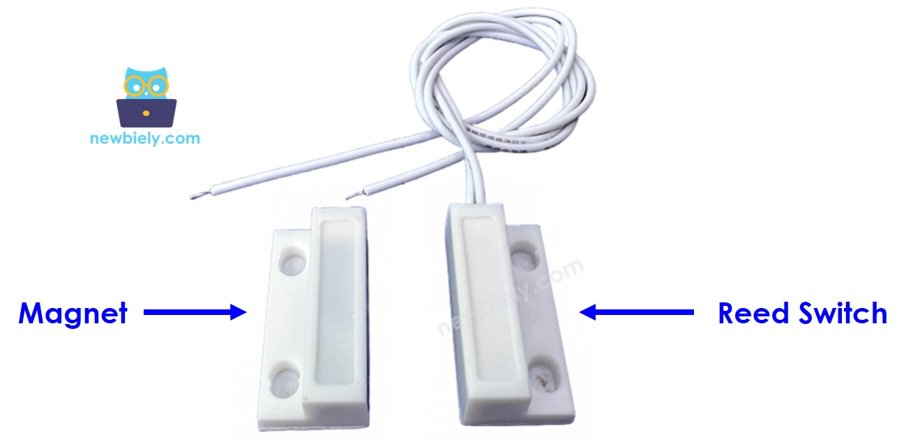
Similar to a regular switch/button, there is no need to differentiate between the two pins of the reed switch.
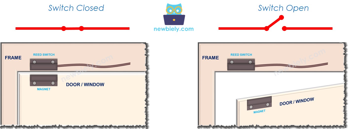
How It Works
The magnet is affixed to the door/window (the movable component), and the reed switch is attached to the door frame (the stationary part). When the door is shut, the two components are in contact:
- If the magnet is close to the reed switch, the reed switch circuit is closed
- If the magnet is distant from the reed switch, the reed switch circuit is open
※ NOTE THAT:
The reed switch does not produce a LOW or HIGH signal on its pins. It is either closed or open. Depending on how we connect it to the ESP8266, the value of the pin can be LOW, HIGH, or an unpredictable floating value. To avoid this, a pull-up or pull-down resistor should be used on the ESP8266 pin.
If we attach a pin of the reed switch to GND and the other pin of the reed switch to an ESP8266 input pin with a pull-up resistor (internal or external):
- When the magnet is close to the reed switch, the value in the ESP8266 input pin is LOW
- When the magnet is distant from the reed switch, the value in the ESP8266 input pin is HIGH
To determine the status of the door, we simply check the state of the Arduino's input pin:
- If the state is LOW, the door is closed
- If the state is HIGH, the door is opened
We can also detect when the door opens or closes by monitoring the state changes on the ESP8266 input pin:
- If the state changes from LOW to HIGH, The door-opening has been detected
- If the state changes from HIGH to LOW, The door-closing has been detected
Wiring Diagram
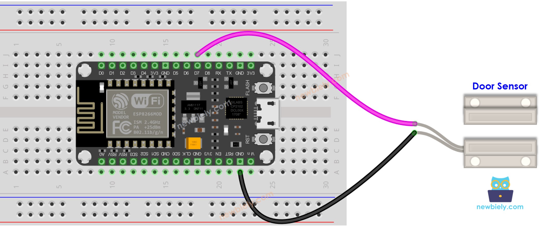
This image is created using Fritzing. Click to enlarge image
See more in ESP8266's pinout and how to supply power to the ESP8266 and other components.
How To Program For Door Sensor
- Sets the ESP8266 pin to digital input mode by utilizing the pinMode() function. As an example, pin D7 is set as an input.
- Utilizes the digitalRead() function to assess the state of the ESP8266 pin.
ESP8266 Code - Check Door Open and Close State
Detailed Instructions
To get started with ESP8266 on Arduino IDE, follow these steps:
- Check out the how to setup environment for ESP8266 on Arduino IDE tutorial if this is your first time using ESP8266.
- Wire the components as shown in the diagram.
- Connect the ESP8266 board to your computer using a USB cable.
- Open Arduino IDE on your computer.
- Choose the correct ESP8266 board, such as (e.g. NodeMCU 1.0 (ESP-12E Module)), and its respective COM port.
- Copy the code and open it with the Arduino IDE.
- Click the Upload button in the IDE to send the code to the ESP8266.
- Bring the magnet close to the reed switch, then move it away.
- Check the Serial Monitor for the result.
ESP8266 Code - Detect Door-opening and Door-closing Events
- Copy the code and open it in the Arduino IDE.
- Click the Upload button to transfer it to the ESP8266.
- Bring the magnet close to the reed switch, then move it away.
- Check out the result on the Serial Monitor.