ESP8266 - Water Sensor
This tutorials instructs you how to use the water sensor with ESP8266. We will learn:
- How to connect the water sensor to ESP8266
- How to program ESP8266 to read the state from the water sensor.
- How to detect water leakage, rainfall, tank overflow, and measure the water level.
- How to calibrate the water sensor.
Hardware Preparation
Or you can buy the following kits:
| 1 | × | DIYables Sensor Kit (18 sensors/displays) |
Additionally, some of these links are for products from our own brand, DIYables .
Overview of Water Level Sensor
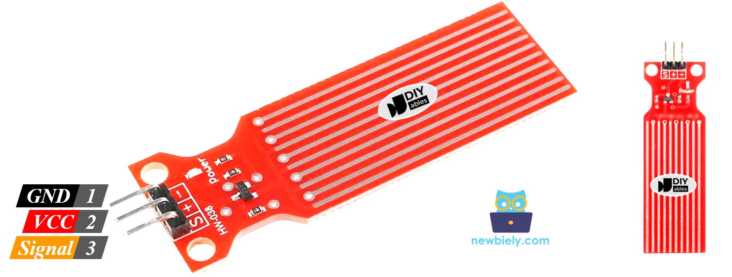
Water Level Sensor Pinout
The water level sensor has 3 pins:
- The S (Signal) pin is an analog output that should be connected to one of the analog inputs on your ESP8266.
- The + (VCC) pin supplies power for the sensor and it is suggested to use a voltage between 3.3V – 5V.
- The - (GND) pin is a ground connection.
How Water Level Sensor Works
In short, the output voltage on the signal pin increases as the sensor is exposed to more water.
Let's take a closer look.
The sensor has a set of ten exposed copper traces, with five being power traces and the other five being sense traces. The traces are arranged in parallel, with one sense trace between every two power traces. Unless submerged in water, these traces are not connected.
The traces act as a variable resistor (just like a potentiometer) whose resistance varies according to the water level:
- The resistance of the traces is inversely proportional to the height of the water.
- The greater the amount of water the sensor is immersed in, the better the conductivity is, resulting in a lower resistance.
- The lesser the amount of water the sensor is immersed in, the worse the conductivity is, resulting in a higher resistance.
- The output voltage of the sensor is determined by the resistance.
Assessing the voltage can be used to ascertain the water level.
Wiring Diagram
In theory, the VCC and GND pins of the sensor can be connected to the 5v and GND pins of ESP8266, respectively, in order to provide power to the sensor.
However, it is not advised to use this method in practice. If the environment is humid, supplying power to the sensor constantly will cause it to corrode electrochemically at a faster rate, thus reducing its lifespan. To prevent this, we suggest powering the sensor only when you need to read its value. This can be done by connecting the sensor's VCC pin to a digital pin of an ESP8266 and setting the Arduino's pin to HIGH before reading and LOW after.
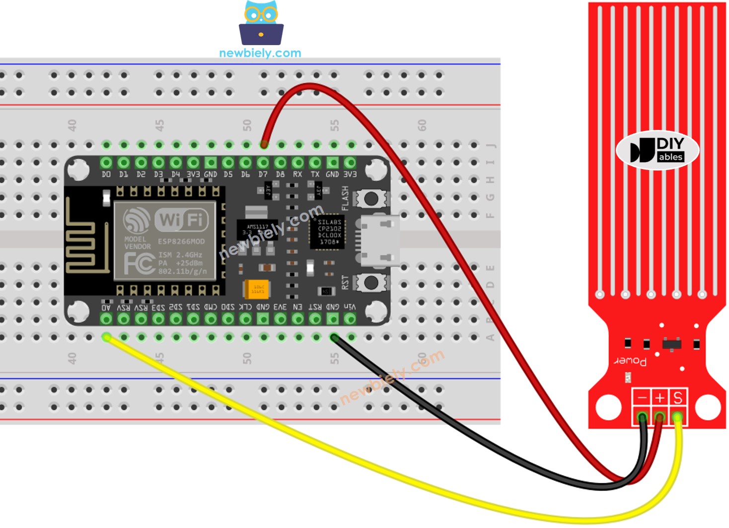
This image is created using Fritzing. Click to enlarge image
ESP8266 Code - Reading Value from Water Sensor
Detailed Instructions
To get started with ESP8266 on Arduino IDE, follow these steps:
- Check out the how to setup environment for ESP8266 on Arduino IDE tutorial if this is your first time using ESP8266.
- Wire the components as shown in the diagram.
- Connect the ESP8266 board to your computer using a USB cable.
- Open Arduino IDE on your computer.
- Choose the correct ESP8266 board, such as (e.g. NodeMCU 1.0 (ESP-12E Module)), and its respective COM port.
- Copy the code and open it with the Arduino IDE.
- Click the Upload button on the Arduino IDE to compile and upload the code to the ESP8266.
- Gently lower the sensor into a glass of water.
- View the outcome on the Serial Monitor; the value should be 0 when the sensor is not in contact with anything.
※ NOTE THAT:
The sensor should not be completely submerged; only the exposed traces on the PCB should come into contact with water. Please take care when installing it.
How To Detect Water Leakage
To identify water leakage, rainfall, and tank overflow, we just need to compare the reading value with a threshold value that is determined during the calibration section of this tutorial.
Let us consider a particular instance. If water is detected, ESP8266 will activate an LED.
Wiring Diagram
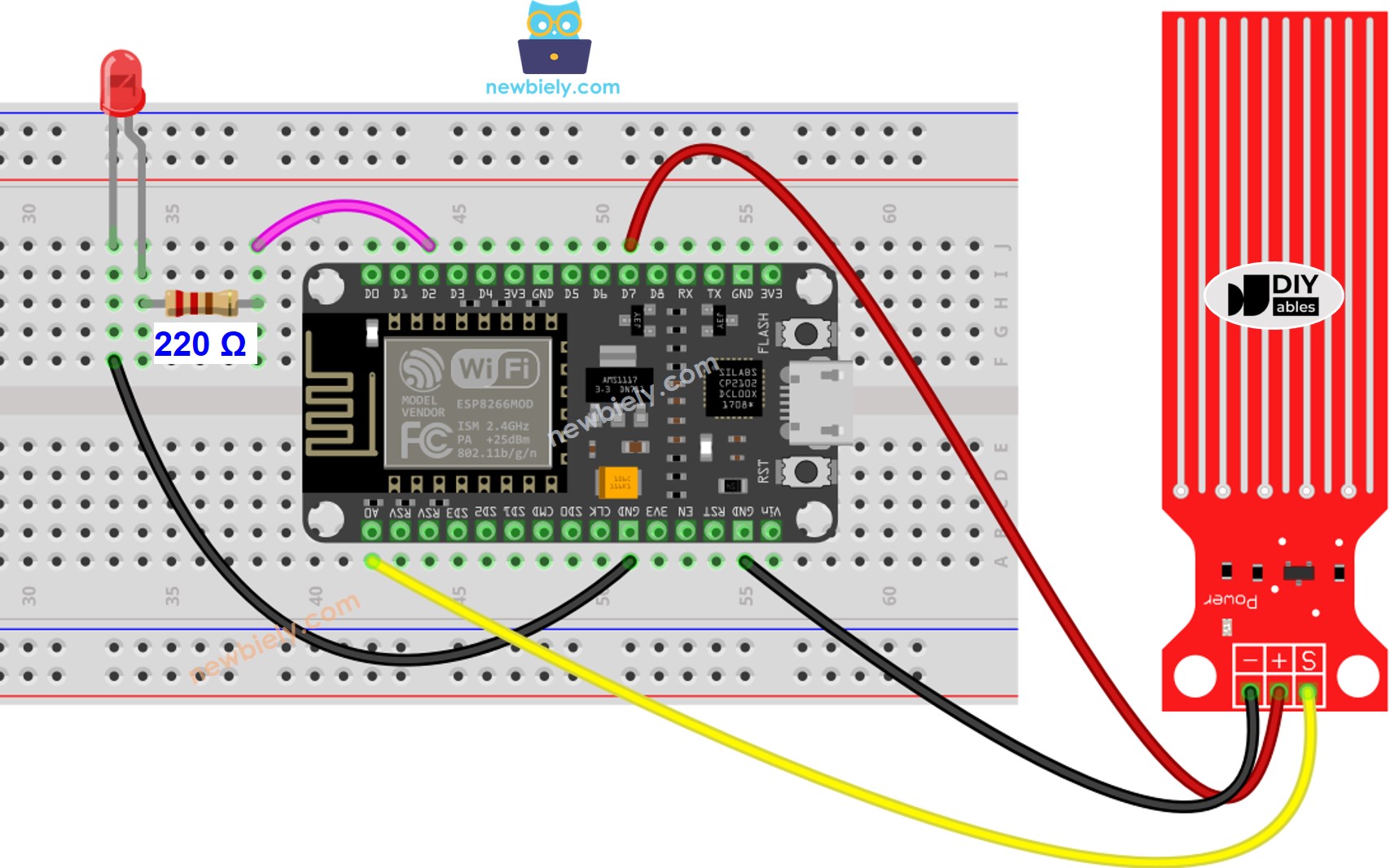
This image is created using Fritzing. Click to enlarge image
See more in ESP8266's pinout and how to supply power to the ESP8266 and other components.
ESP8266 Code - Detecting Water Leakage
How To Measure The Water Level
If you wish to measure the current level of water by splitting the maximum height into various levels, the following code can be used. Note that the maximum height of the water is equivalent to the height of the sensor. This code divides the maximum height into four levels.
※ NOTE THAT:
- SENSOR_MIN and SENSOR_MAX are determined through the calibration process.
- The mapping method mentioned above is not precise. Nevertheless, it is suitable for many applications. If you wish to make the results more accurate, you can measure the threshold values for each level. For further information, please refer to the calibration section at the end of this tutorial.
Water Level Sensor Calibration
The output value of the sensor is determined by two factors: the water level and the conductivity of the water. Pure water is not conductive, however, when minerals and impurities are present, it becomes conductive. The more conductive the water is, the higher the sensitivity of the sensor. Additionally, the output value is also affected by the voltage supplied to the VCC pin of the sensor.
For accurate readings from the water sensor, we suggest calibrating it for the specific type of water you intend to monitor.
Prior to setting the threshold for initiating an action, it is necessary to measure the actual value obtained from the sensor through a test.
Instructions for the test:
- Utilize the sketch provided above to read the sensor value.
- Immerse the sensor in the water, making sure it is at the desired threshold level.
- Record the value outputted by the sensor in the Serial Monitor.
- Use this value as the threshold to trigger a certain action.
It may require some experimentation to complete this test.
The test can also be used to discover:
- SENSOR_MIN value, when the sensor is not submerged in the liquid
- SENSOR_MAX value, when the sensor is totally submerged in the liquid
- A limit value for spotting water leakage
- The boundary values for each stage of your degree scale.
※ NOTE THAT:
This tutorial uses the analogRead() function to get data from an ADC (Analog-to-Digital Converter) that's connected to a sensor or another part. The ESP8266's ADC works well for projects where you don't need very precise readings. But remember, the ESP8266's ADC isn't very accurate for detailed measurements. If your project needs to be very precise, you might want to use a separate ADC like the ADS1115 with the ESP8266, or use Arduino like the Arduino Uno R4 WiFi, which has a more reliable ADC.
Video Tutorial
Challenge Yourself
- Upon detecting water leakage,
- Send an email,
- Send a SMS message,
- And make a sound alarm.