ESP8266 - Door Sensor - Servo Motor
This tutorial instructs you how to use ESP8266 and door sensor to control servo motor. In detail:
- When the door is open, ESP8266 rotates servo motor to 90 degree
- Should the door open again, ESP8266s rotates servo motor back to 0 degree.
The above process are repeated infinitely.
Hardware Preparation
Or you can buy the following kits:
| 1 | × | DIYables Sensor Kit (30 sensors/displays) | |
| 1 | × | DIYables Sensor Kit (18 sensors/displays) |
Additionally, some of these links are for products from our own brand, DIYables .
Overview of Servo Motor and Door Sensor
If you are unfamiliar with servo motor and door sensor (including pinout, operation, and programming), the following tutorials can help:
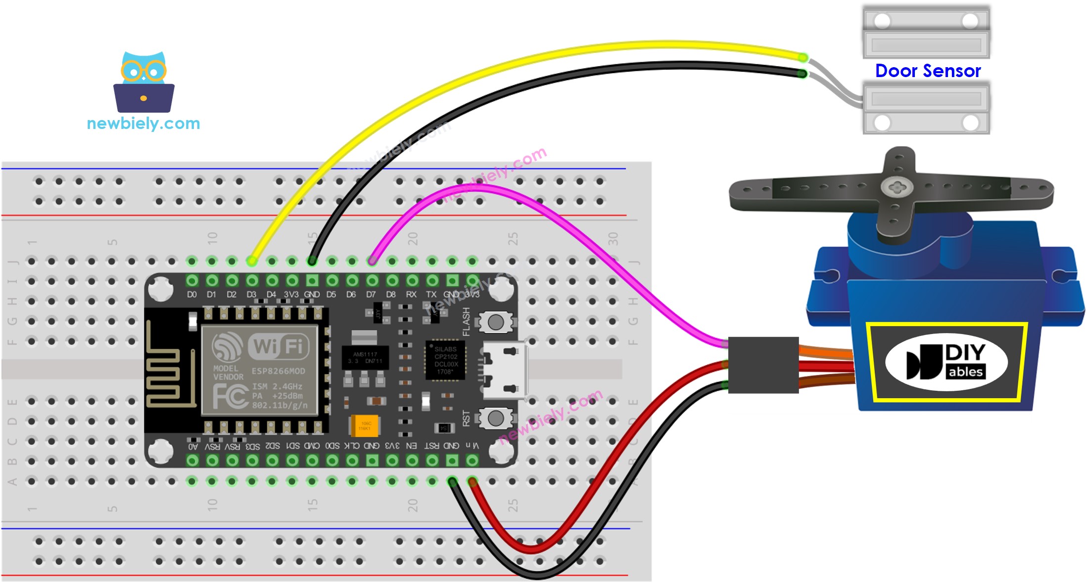
Wiring Diagram

This image is created using Fritzing. Click to enlarge image
See more in ESP8266's pinout and how to supply power to the ESP8266 and other components.
Please note that the wiring diagram shown above is only suitable for a servo motor with low torque. In case the motor vibrates instead of rotating, an external power source must be utilized to provide more power for the servo motor. The below demonstrates the wiring diagram with an external power source for servo motor.
TO BE ADD IMAGE
Please do not forget to connect GND of the external power to GND of ESP8266.
ESP8266 Code - Door Sensor Controls Servo Motor
Detailed Instructions
To get started with ESP8266 on Arduino IDE, follow these steps:
- Check out the how to setup environment for ESP8266 on Arduino IDE tutorial if this is your first time using ESP8266.
- Wire the components as shown in the diagram.
- Connect the ESP8266 board to your computer using a USB cable.
- Open Arduino IDE on your computer.
- Choose the correct ESP8266 board, such as (e.g. NodeMCU 1.0 (ESP-12E Module)), and its respective COM port.
- Attach ESP8266 to the computer using a USB cable.
- Open the Arduino IDE, select the correct board and port.
- Copy the code above and open it in the Arduino IDE.
- Click the Upload button on the Arduino IDE to compile and upload the code to the ESP8266.
- Bring the magnet close to the reed switch and then move it away from the reed switch. Do this multiple times.
- Check out the servo motor angle change.
