ESP8266 - Potentiometer LED

In a previous tutorial, We have learned how to change the brightness of LED according to the potentiometer's output value.

This tutorial instructs you how to use ESP8266 and potentiometer to control LED. In detail:

Hardware Preparation

1×ESP8266 NodeMCU
1×Micro USB Cable
1×Potentiometer
1×LED
1×220 ohm resistor
1×Breadboard
1×Jumper Wires
1×(Optional) 5V Power Adapter for ESP8266
1×(Optional) ESP8266 Screw Terminal Adapter

Or you can buy the following sensor kit:

1×DIYables Sensor Kit 30 types, 69 units
Disclosure: Some of the links provided in this section are Amazon affiliate links. We may receive a commission for any purchases made through these links at no additional cost to you. We appreciate your support.

Overview of LED and Potentiometer

If you are unfamiliar with LED and potentiometer (pinout, functionality, programming ...), the following tutorials can provide more information:

Wiring Diagram

The wiring diagram between ESP8266 NodeMCU and Potentiometer LED

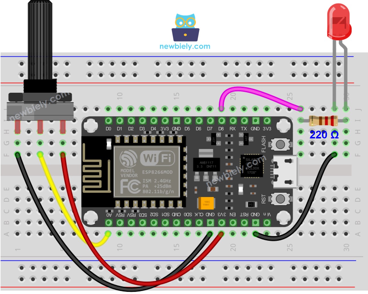
This image is created using Fritzing. Click to enlarge image

See more in ESP8266's pinout and how to supply power to the ESP8266 and other components.

ESP8266 Code - Analog Threshold

/* * This ESP8266 NodeMCU code was developed by newbiely.com * * This ESP8266 NodeMCU code is made available for public use without any restriction * * For comprehensive instructions and wiring diagrams, please visit: * https://newbiely.com/tutorials/esp8266/esp8266-potentiometer-led */ const int POTENTIOMETER_PIN = A0; // The ESP8266 pin connected to Potentiometer pin const int LED_PIN = D8; // The ESP8266 pin connected to LED's pin // The setup function runs once on reset or power-up void setup() { // Initialize the Serial to communicate with the Serial Monitor. Serial.begin(9600); // declare LED pin to be an output: pinMode(LED_PIN, OUTPUT); } // The loop function repeats indefinitely. void loop() { // reads the input on analog pin A0 (value between 0 and 1023) int analog_value = analogRead(POTENTIOMETER_PIN); // scales it to brightness (value between 0 and 255) int brightness = map(analog_value, 0, 1023, 0, 255); // sets the brightness LED that connects to pin 3 analogWrite(LED_PIN, brightness); // print out the value Serial.print("Analog: "); Serial.print(analog_value); Serial.print(", Brightness: "); Serial.println(brightness); delay(100); }

Detailed Instructions

To get started with ESP8266 on Arduino IDE, follow these steps:

  • Check out the how to setup environment for ESP8266 on Arduino IDE tutorial if this is your first time using ESP8266.
  • Wire the components as shown in the diagram.
  • Connect the ESP8266 board to your computer using a USB cable.
  • Open Arduino IDE on your computer.
  • Choose the correct ESP8266 board, such as (e.g. NodeMCU 1.0 (ESP-12E Module)), and its respective COM port.
  • Plug the USB cable into your ESP8266 and PC.
  • Launch the Arduino IDE, select the correct board and port.
  • Copy the code and open it in the Arduino IDE.
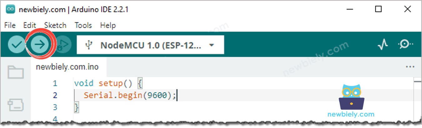
  • Click the Upload button in the Arduino IDE to compile and upload the code to your ESP8266.
Arduino IDE Upload Code
  • Turn the potentiometer
  • Check out the alteration in the LED's condition

Code Explanation

Check out the line-by-line explanation contained in the comments of the source code!

ESP8266 Code - Voltage Threshold

A potentiometer's analog value is transformed into a voltage value. This voltage value is then compared to a voltage threshold, which will cause an LED to be triggered.

/* * This ESP8266 NodeMCU code was developed by newbiely.com * * This ESP8266 NodeMCU code is made available for public use without any restriction * * For comprehensive instructions and wiring diagrams, please visit: * https://newbiely.com/tutorials/esp8266/esp8266-potentiometer-led */ #define POTENTIOMETER_PIN A0 // The ESP8266 pin connected to Potentiometer pin #define LED_PIN D8 // The ESP8266 pin connected to LED's pin #define VOLTAGE_THRESHOLD 2.5 // Voltages void setup() { pinMode(LED_PIN, OUTPUT); // Configure the ESP8266 pin to the output mode } void loop() { int analog_value = analogRead(POTENTIOMETER_PIN); // read the input on analog pin float voltage = floatMap(analog_value, 0, 1023, 0, 5); // Rescale to potentiometer's voltage if (voltage > VOLTAGE_THRESHOLD) digitalWrite(LED_PIN, HIGH); // turn on LED else digitalWrite(LED_PIN, LOW); // turn off LED } float floatMap(float x, float in_min, float in_max, float out_min, float out_max) { return (x - in_min) * (out_max - out_min) / (in_max - in_min) + out_min; }

Video Tutorial

※ OUR MESSAGES

  • As freelancers, We are AVAILABLE for HIRE. See how to outsource your project to us
  • Please feel free to share the link of this tutorial. However, Please do not use our content on any other websites. We invested a lot of effort and time to create the content, please respect our work!