ESP8266 - Button - Relay

This tutorial instructs you how to use the ESP8266 and button to control the relay. By connecting the relay to a soleniod lock, light bulb, LED strip, motor, or actuator..., we can use a button to control the them. We will learn two different applications:

Application 1 - The relay state is synchronized with the button state. In detail:

Application 2 - The relay state is toggled each time the button is pressed. More specifically:

In the Application 2, We need to debounce the button to make sure it works properly. We'll see why it's important by comparing how the relay behaves when we use the ESP8266 code with and without debouncing the button.

Hardware Preparation

1×ESP8266 NodeMCU
1×Micro USB Cable
1×Push Button
1×(Optional) Panel-mount Push Button
1×Relay
1×Breadboard
1×Jumper Wires
1×(Optional) Solenoid Lock
1×(Optional) 12V Power Adapter
1×(Optional) DC Power Jack
1×(Optional) 5V Power Adapter for ESP8266
1×(Optional) ESP8266 Screw Terminal Adapter

Or you can buy the following sensor kit:

1×DIYables Sensor Kit 30 types, 69 units
Disclosure: Some of the links provided in this section are Amazon affiliate links. We may receive a commission for any purchases made through these links at no additional cost to you. We appreciate your support.

Overview of Relay and Button

If you are unfamiliar with relay and button (including pinout, operation, and programming), the following tutorials can help:

Wiring Diagram

The wiring diagram between ESP8266 NodeMCU and Button relay

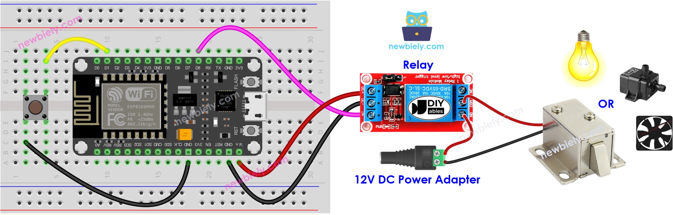
This image is created using Fritzing. Click to enlarge image

See more in ESP8266's pinout and how to supply power to the ESP8266 and other components.

Application 1 - The relay state is in sync with the button state

ESP8266 Code

/* * This ESP8266 NodeMCU code was developed by newbiely.com * * This ESP8266 NodeMCU code is made available for public use without any restriction * * For comprehensive instructions and wiring diagrams, please visit: * https://newbiely.com/tutorials/esp8266/esp8266-button-relay */ #define BUTTON_PIN D1 // The ESP8266 pin D1 connected to button's pin #define RELAY_PIN D7 // The ESP8266 pin D7 connected to relay's pin void setup() { Serial.begin(9600); // Initialize the Serial to communicate with the Serial Monitor. pinMode(BUTTON_PIN, INPUT_PULLUP); // Configure the ESP8266 pin to the input pull-up mode pinMode(RELAY_PIN, OUTPUT); // Configure the ESP8266 pin to the output mode } void loop() { int button_state = digitalRead(BUTTON_PIN); // read new state if (button_state == LOW) { Serial.println("The button is being pressed"); digitalWrite(RELAY_PIN, HIGH); // turn on } else if (button_state == HIGH) { Serial.println("The button is unpressed"); digitalWrite(RELAY_PIN, LOW); // turn off } }

Detailed Instructions

To get started with ESP8266 on Arduino IDE, follow these steps:

  • Check out the how to setup environment for ESP8266 on Arduino IDE tutorial if this is your first time using ESP8266.
  • Wire the components as shown in the diagram.
  • Connect the ESP8266 board to your computer using a USB cable.
  • Open Arduino IDE on your computer.
  • Choose the correct ESP8266 board, such as (e.g. NodeMCU 1.0 (ESP-12E Module)), and its respective COM port.
  • Connect an ESP8266 to your computer with a USB cable.
  • Launch the Arduino IDE, and select the correct board and port.
  • Copy the code and open it in the Arduino IDE.
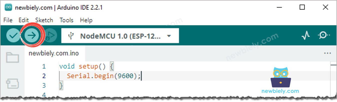
  • Click the Upload button on the Arduino IDE to compile and upload the code to the ESP8266.
Arduino IDE Upload Code
  • Press the button and hold it for a few seconds.
  • Check out the change in the relay's condition.

You will see that the relay state is in sync with the button state.

Code Explanation

Check out the line-by-line explanation contained in the comments of the source code!

Application 2 - Button toggles Relay

ESP8266 Code - Button Toggles relay Without Debouncing

/* * This ESP8266 NodeMCU code was developed by newbiely.com * * This ESP8266 NodeMCU code is made available for public use without any restriction * * For comprehensive instructions and wiring diagrams, please visit: * https://newbiely.com/tutorials/esp8266/esp8266-button-relay */ #define BUTTON_PIN D1 // The ESP8266 pin D1 connected to button's pin #define RELAY_PIN D7 // The ESP8266 pin D7 connected to relay's pin int relay_state = LOW; // The current state of relay int button_state; // The current state of button int last_button_state; // The previous state of button void setup() { Serial.begin(9600); // Initialize the Serial to communicate with the Serial Monitor. pinMode(BUTTON_PIN, INPUT_PULLUP); // Configure the ESP8266 pin to the input pull-up mode pinMode(RELAY_PIN, OUTPUT); // Configure the ESP8266 pin to the output mode button_state = digitalRead(BUTTON_PIN); } void loop() { last_button_state = button_state; // save the last state button_state = digitalRead(BUTTON_PIN); // read new state if (last_button_state == HIGH && button_state == LOW) { Serial.println("The button is pressed"); // toggle state of relay relay_state = !relay_state; // control relay according to the toggled state digitalWrite(RELAY_PIN, relay_state); } }

Code Explanation

You can locate the explanation in the comment lines of the ESP8266 code above.

In the code, the expression relay_state = !relay_state is equivalent to the following code:

if(relay_state == LOW) relay_state = HIGH; else relay_state = LOW;

Detailed Instructions

  • Copy the code and open it in the Arduino IDE.
  • Upload the code to the ESP8266.
  • Press release and button several times.
  • Check out the change in the relay's state.

You might notice that the relay switches on or off every time you press the button, but it may not always be the same. Sometimes it may rapidly switch multiple times with just one button press, or it might not switch at all (switch twice very quickly, which can't see with the naked eye).

⇒ To solve this problem, we need to debounce for the button.

ESP8266 Code - Button Toggles relay With Debouncing

Debouncing a button can be challenging for beginners. Fortunately, the ezButton library makes it easy.

Why is debouncing necessary? See the ESP8266 - Button Debounce tutorial for more information.

/* * This ESP8266 NodeMCU code was developed by newbiely.com * * This ESP8266 NodeMCU code is made available for public use without any restriction * * For comprehensive instructions and wiring diagrams, please visit: * https://newbiely.com/tutorials/esp8266/esp8266-button-relay */ #include <ezButton.h> #define BUTTON_PIN D1 // The ESP8266 pin D1 connected to button's pin #define RELAY_PIN D7 // The ESP8266 pin D7 connected to relay's pin ezButton button(BUTTON_PIN); // create ezButton object for pin 7; int relay_state = LOW; // The current state of relay void setup() { Serial.begin(9600); // Initialize the Serial to communicate with the Serial Monitor. pinMode(RELAY_PIN, OUTPUT); // Configure the ESP8266 pin to the output mode button.setDebounceTime(50); // set debounce time to 50 milliseconds } void loop() { button.loop(); // MUST call the loop() function first if (button.isPressed()) { Serial.println("The button is pressed"); // toggle state of relay relay_state = !relay_state; // control relay according to the toggled state digitalWrite(RELAY_PIN, relay_state); } }

Detailed Instructions

  • Install the ezButton library. Refer to How To for instructions.
  • Copy the code and open it with Arduino IDE.
  • Click the Upload button on Arduino IDE to upload the code to the ESP8266.
  • Press and release the button multiple times.
  • Check out the relay's state change.

You'll notice that the relay will switch on or off only one time whenever you press the button.

Video Tutorial

※ OUR MESSAGES

  • As freelancers, We are AVAILABLE for HIRE. See how to outsource your project to us
  • Please feel free to share the link of this tutorial. However, Please do not use our content on any other websites. We invested a lot of effort and time to create the content, please respect our work!