ESP8266 - Light Sensor LED
This tutorial instructs you how to use ESP8266 and light sensor to trigger LED. In detail:
- When the reading value from the light sensor is lower than a certain threshold, ESP8266 turns the LED on.
- When the reading value from the light sensor is greater than a certain threshold, ESP8266 turns the LED off.
The light sensor is also known as photoresistor, light-dependent resistor, photocell, LDR. The ESP8266 utilizes a light sensor to measure the ambient light level. If the environment is dim, the ESP8266 turns on the LED, and if it's bright, the LED will be turned off.
Hardware Preparation
Or you can buy the following kits:
| 1 | × | DIYables Sensor Kit (18 sensors/displays) |
Additionally, some of these links are for products from our own brand, DIYables .
Buy Note: Use the LED Module for easier wiring. It includes an integrated resistor.
The LDR light sensor is very affordable, but it requires a resistor for wiring, which can make the setup more complex. To simplify the wiring, you can use an LDR light sensor module as an alternative.
Overview of LED and Light Sensor
If you are unfamiliar with LED and light sensor (including pinout, how it works, and how to program), the following tutorials can help:
Wiring Diagram
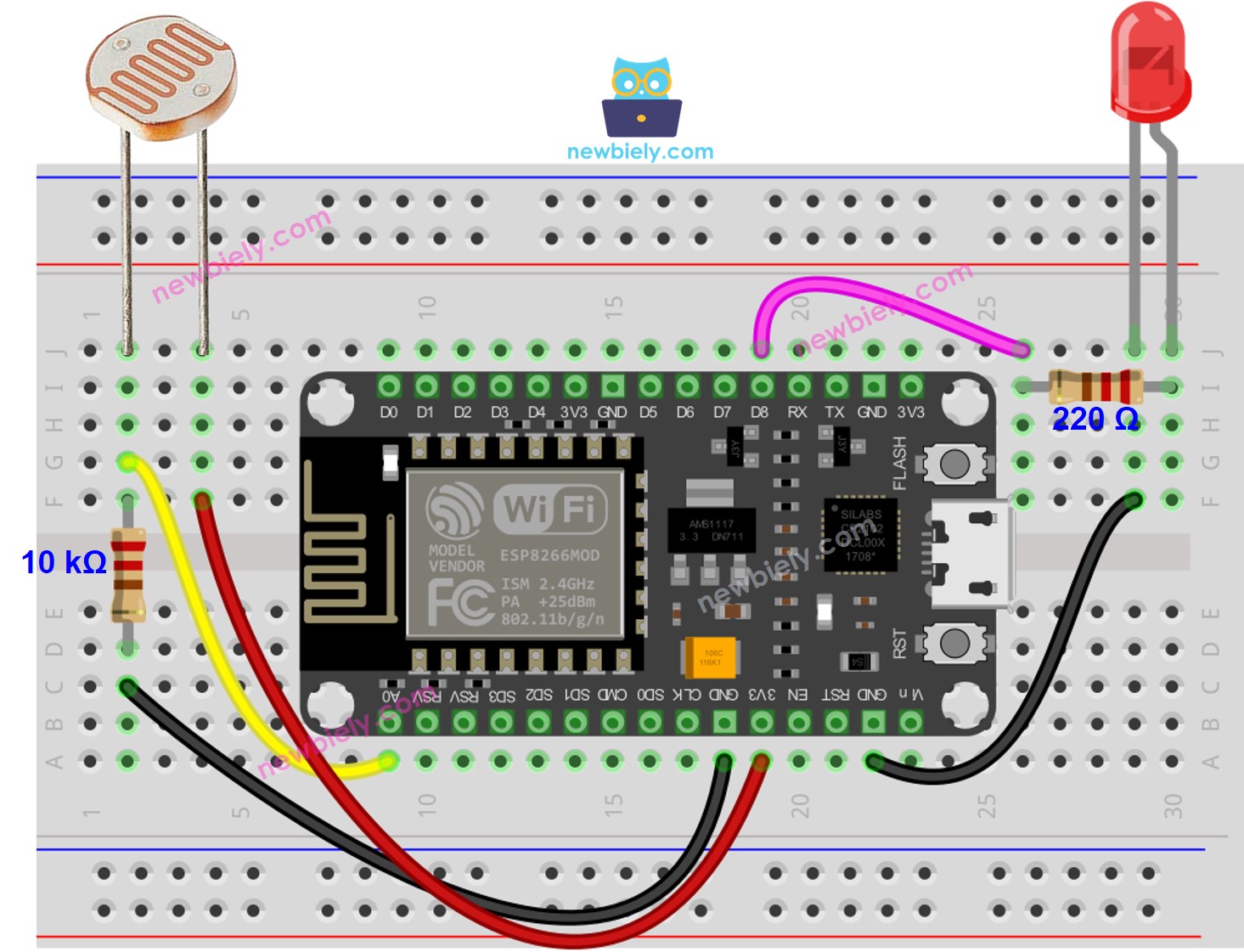
This image is created using Fritzing. Click to enlarge image
See more in ESP8266's pinout and how to supply power to the ESP8266 and other components.
ESP8266 Code
Detailed Instructions
To get started with ESP8266 on Arduino IDE, follow these steps:
- Check out the how to setup environment for ESP8266 on Arduino IDE tutorial if this is your first time using ESP8266.
- Wire the components as shown in the diagram.
- Connect the ESP8266 board to your computer using a USB cable.
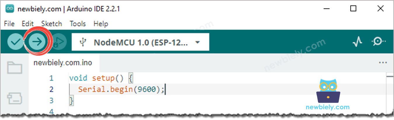
- Open Arduino IDE on your computer.
- Choose the correct ESP8266 board, such as (e.g. NodeMCU 1.0 (ESP-12E Module)), and its respective COM port.
- Plug the USB cable into the ESP8266 and the PC.
- Launch the Arduino IDE, choose the correct board and port.
- Copy the code and open it in the Arduino IDE.
- Click the Upload button in the Arduino IDE to compile and upload the code to the ESP8266.
- Emit light source towards the sensor
- Check out the LED's state
Code Explanation
Check out the line-by-line explanation contained in the comments of the source code!