ESP8266 - Touch Sensor - Relay
This tutorial instructs you how to use the ESP8266 and touch sensor to control the relay. By connecting the relay to a soleniod lock, light bulb, LED strip, motor, or actuator..., we can use a touch sensor to control the them. We will learn two different applications:
Application 1 - The relay state is synchronized with the touch sensor state. In detail:
- ESP8266 turns on the relay when the touch sensor is being touched.
- ESP8266 turns off the relay when the touch sensor is NOT being touched.
Application 2 - The relay state is toggled each time the touch sensor is touched. More specifically:
- If ESP8266 detects that the touch sensor has been touched (changing from a HIGH state to a LOW state), it will turn ON the relay if it's currently OFF, or turn OFF the relay if it's currently ON.
- Releasing the touch sensor does not affect to the relay state.
Hardware Preparation
Or you can buy the following kits:
| 1 | × | DIYables Sensor Kit (18 sensors/displays) |
Additionally, some of these links are for products from our own brand, DIYables .
Overview of Relay and Touch Sensor
If you are unfamiliar with relay and touch sensor (including pinout, operation, and programming), the following tutorials can help:
Wiring Diagram
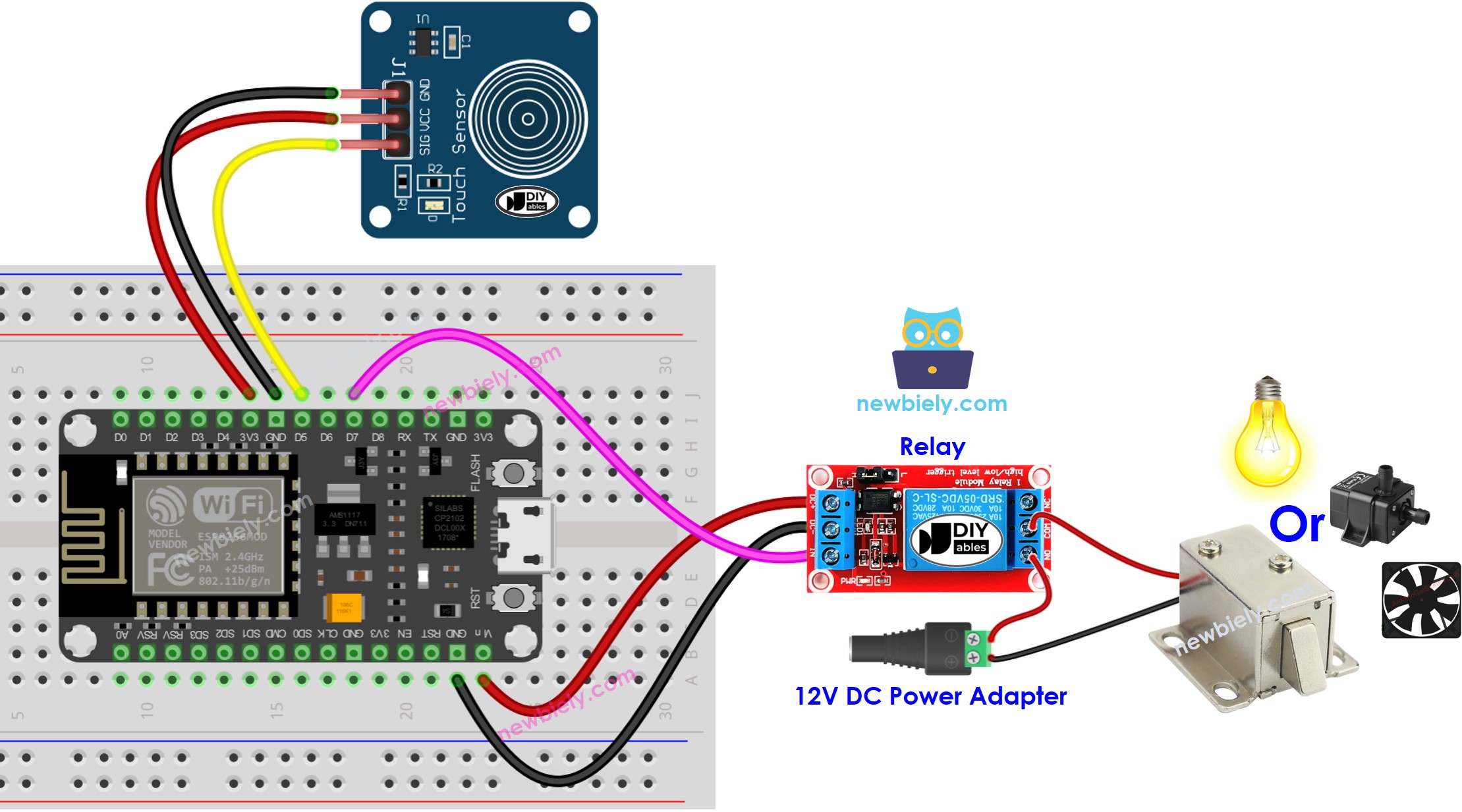
This image is created using Fritzing. Click to enlarge image
See more in ESP8266's pinout and how to supply power to the ESP8266 and other components.
Application 1 - The relay state is in sync with the touch sensor state
ESP8266 Code
Detailed Instructions
To get started with ESP8266 on Arduino IDE, follow these steps:
- Check out the how to setup environment for ESP8266 on Arduino IDE tutorial if this is your first time using ESP8266.
- Wire the components as shown in the diagram.
- Connect the ESP8266 board to your computer using a USB cable.
- Open Arduino IDE on your computer.
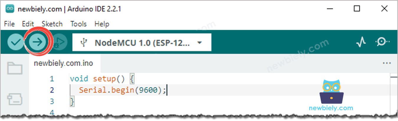
- Choose the correct ESP8266 board, such as (e.g. NodeMCU 1.0 (ESP-12E Module)), and its respective COM port.
- Connect an ESP8266 to your computer with a USB cable.
- Launch the Arduino IDE, and select the correct board and port.
- Copy the code and open it in the Arduino IDE.
- Click the Upload button on the Arduino IDE to compile and upload the code to the ESP8266.
- Touch the touch sensor and hold it for a few seconds.
- Check out the change in the relay's condition.
You will see that the relay state is in sync with the touch sensor state.
Code Explanation
Check out the line-by-line explanation contained in the comments of the source code!
Application 2 - Touch Sensor toggles Relay
ESP8266 Code - Touch Sensor toggles Relay
Code Explanation
You can locate the explanation in the comment lines of the ESP8266 code above.
In the code, the expression relay_state = !relay_state is equivalent to the following code:
Detailed Instructions
- Copy the code and open it in the Arduino IDE.
- Upload the code to the ESP8266.
- Touch and release the touch sensor several times.
- Check out the change in the relay's state.
You'll notice that the relay will switch on or off one time whenever you Touch the touch sensor.