ESP8266 - Potentiometer
This tutorial instructs you how to use ESP8266 with a potentiometer, which is also known as pot, trimmer, variable resistor, rheostat, or rotary angle sensor. In detail, we will learn:
- How potentiometer works.
- How to connect a potentiometer to ESP8266.
- How to program ESP8266 to read the value from the potentiometer
- How to convert the read value to another value such as voltage, angle of servo motor, speed of motor, brightness of LED...
Hardware Preparation
Or you can buy the following kits:
| 1 | × | DIYables Sensor Kit (18 sensors/displays) |
Additionally, some of these links are for products from our own brand, DIYables .
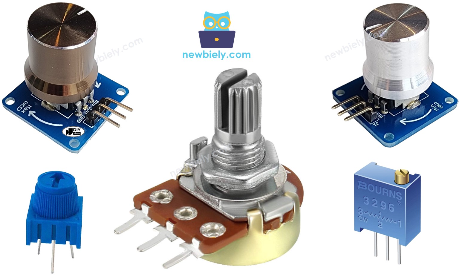
Overview of Potentiometer
A rotary potentiometer is also known as pot, trimmer, variable resistor, rheostat, or rotary angle sensor. It is used to manually adjust the value of something. Examples include the volume of a stereo, the brightness of a lamp, and the zoom level of an oscilloscope.
The Potentiometer Pinout
A Potentiometer typically has three pins:
- The GND pin should be connected to the ground (0V).
- The VCC pin should be connected to the voltage source (5V or 3.3V).
- The output pin sends the voltage to the Arduino's input pin.
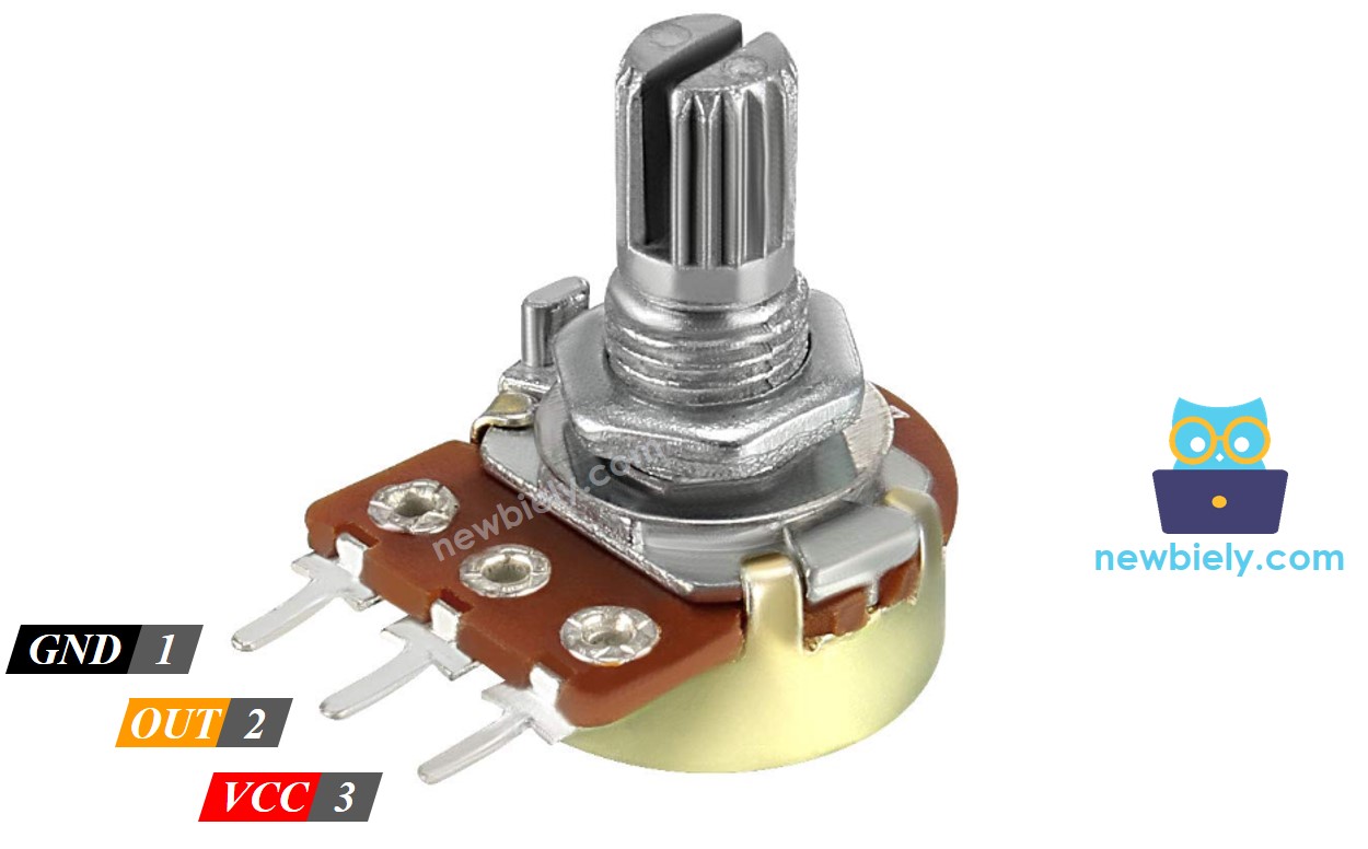
※ NOTE THAT:
The GND and VCC pins can be swapped.
How It Works
The rotation of the potentiometer's shaft can be from 0°, which is closest to GND, to a maximum angle, which is closest to the VCC pin, referred to as ANGLE_MAX.
※ NOTE THAT:
The value of ANGLE_MAX is determined by the manufacturer. Generally, we do not need to consider this value unless we are computing a rotated angle (see the use cases section).
The working principle:
- An user rotates shaft of the potentiometer
- ⇒ The angle of the potentiometer is changed
- ⇒ The resistance of the potentiometer is changed
- ⇒ The voltage in the output pin of the potentiometer is changed
- ⇒ The analog value read by ESP8266 is changed
ESP8266 - Rotary Potentiometer
Some of ESP8266's pin are capable of functioning as analog input. These analog input pins convert the voltage (ranging from 0v to VCC) into integer values (from 0 to 1023), referred to as ADC value or analog value.
We can connect an output pin of the potentiometer to an analog input pin. This allows us to read the analog value from the pin and convert it into a meaningful value.
The value ESP8266 receives is not an angle or voltage; rather, it is an integer value ranging from 0 to 1023.
Once we have obtained the integer value from the analog input pin, we can rescale this value to a different one. Let us consider the applications.
Use Cases
- Rescale to the angle of the potentiometer.
- Rescale to the voltage of the potentiometer.
- Rescale to a controllable value, such as the volume of a stereo, brightness, or speed of a DC motor - this is the most common use case.
Rescale Range
| FROM | TO | |||
|---|---|---|---|---|
| Angle | rotated by user | 0° | → | ANGLE_MAX |
| Voltage | from potentiometer's pin | 0V | → | VCC |
| ADC value | read by Arduino | 0 | → | 1023 |
| Other value | converted by Arduino | VALUE_MIN | → | VALUE_MAX |
Wiring Diagram
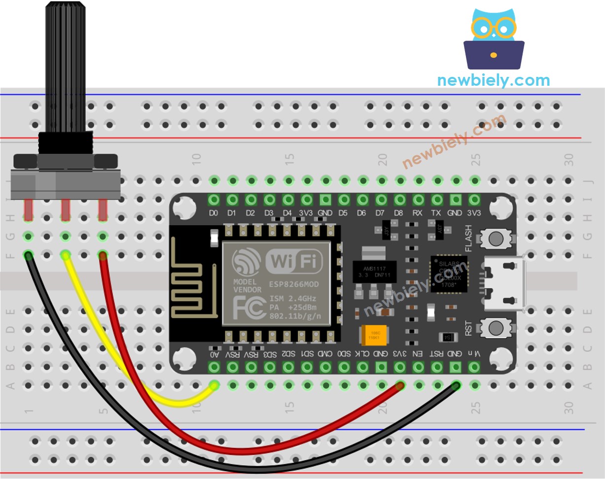
This image is created using Fritzing. Click to enlarge image
See more in ESP8266's pinout and how to supply power to the ESP8266 and other components.
How To Program For Potentiometer
- Access the output pin of the potentiometer with analogRead() and read the value from the input pin.
- Use the map() function to adjust the potentiometer's angle.
- Adjust the voltage to the potentiometer's level.
- Rescale the value to something that can be controlled, such as the volume of a stereo, the brightness, or the speed of a DC motor.
If you desire to adjust the LED from a dim nightlight to its brightest,
※ NOTE THAT:
The map() function is limited to rescaling an analog value to the int or long type. If the controllable value is of float type, the floatMap() function should be used instead of map().
ESP8266 Code
Detailed Instructions
To get started with ESP8266 on Arduino IDE, follow these steps:
- Check out the how to setup environment for ESP8266 on Arduino IDE tutorial if this is your first time using ESP8266.
- Wire the components as shown in the diagram.
- Connect the ESP8266 board to your computer using a USB cable.
- Open Arduino IDE on your computer.
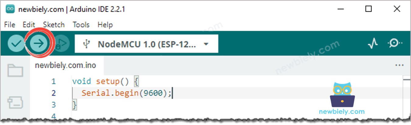
- Choose the correct ESP8266 board, such as (e.g. NodeMCU 1.0 (ESP-12E Module)), and its respective COM port.
- Copy the code and open it in the Arduino IDE.
- Once opened, press the Upload button to transfer the code to the ESP8266.
- Open the Serial Monitor.
- Turn the potentiometer.
- Check out the result on the Serial Monitor.
※ NOTE THAT:
This tutorial uses the analogRead() function to get data from an ADC (Analog-to-Digital Converter) that's connected to a sensor or another part. The ESP8266's ADC works well for projects where you don't need very precise readings. But remember, the ESP8266's ADC isn't very accurate for detailed measurements. If your project needs to be very precise, you might want to use a separate ADC like the ADS1115 with the ESP8266, or use Arduino like the Arduino Uno R4 WiFi, which has a more reliable ADC.
Video Tutorial
Challenge Yourself
Utilize the potentiometer to accomplish one of the following tasks:
- Adjust the position of the servo motor. Tip: Check out arduino - Servo Motor.
- Modify the brightness of LED. Tip: Check out ESP8266 - Fade Led.
Additional Knowledge
- GND and VCC pins can be swapped with no specific convention. All you have to be mindful of is that the voltage value at the output pin will be reversed when these pins are interchanged.