ESP8266 - Heating System
In this tutorial, we will be utilizing the ESP8266, heating element and DS18B20 temperature sensor to control the temperature of a room.
- When the temperature is too low, ESP8266 activates the heating element.
- When the temperature is warm, ESP8266 deactivates the heating element.
Additionally, the code can be adapted for other temperature sensors such as DHT11, DHT22, or LM35 instead of the DS18B20 sensor.
Hardware Preparation
Or you can buy the following kits:
| 1 | × | DIYables Sensor Kit (18 sensors/displays) |
Additionally, some of these links are for products from our own brand, DIYables .
Buy Note: Many DS18B20 sensors available in the market are unreliable. We strongly recommend buying the sensor from the DIYables brand using the link provided above. We tested it, and it worked reliably.
Overview of Heating Element and DS18B20 Temperature Sensor
The heating element utilized in this tutorial requires a 12v power supply. If power is supplied to the heating element, it will generate heat. To control the heating element with ESP8266, a relay must be used as an intermediary.
If you are unfamiliar with temperature sensors and heating elements (pinouts, operation, programming, etc.), the following tutorials can help:
Wiring Diagram
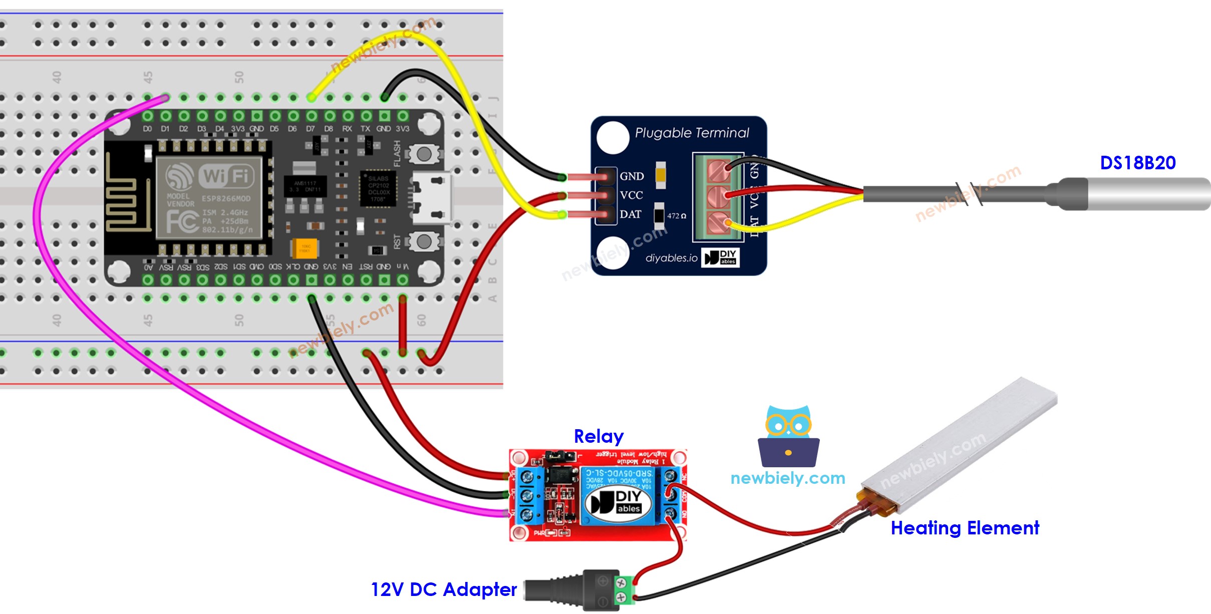
This image is created using Fritzing. Click to enlarge image
See more in ESP8266's pinout and how to supply power to the ESP8266 and other components.
How System Works
- ESP8266 monitors the temperature from the temperature sensor.
- If the temperature drops below a certain lower limit, ESP8266 will activate the heating elements.
- When the temperature exceeds a specific upper limit, ESP8266 will deactivate the heating elements.
The loop is repeated continuously.
ESP8266 Code for Cooling System with DS18B20 sensor
In the code above, when the temperature is lower than 15°C, the ESP8266 will activate the heating element. The heating element will remain on until the temperature rises above 20°C.
Detailed Instructions
To get started with ESP8266 on Arduino IDE, follow these steps:
- Check out the how to setup environment for ESP8266 on Arduino IDE tutorial if this is your first time using ESP8266.
- Wire the components as shown in the diagram.
- Connect the ESP8266 board to your computer using a USB cable.
- Open Arduino IDE on your computer.
- Choose the correct ESP8266 board, such as (e.g. NodeMCU 1.0 (ESP-12E Module)), and its respective COM port.
- Connect your ESP8266 to the computer with a USB cable
- Open the Arduino IDE and select the correct board and port
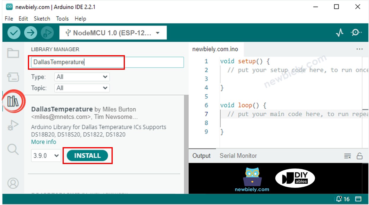
- Click to the Libraries icon on the left bar of the Arduino IDE.
- Search for “Dallas”, then locate the DallasTemperature library by Miles Burton.
- Press the Install button to install the DallasTemperature library.
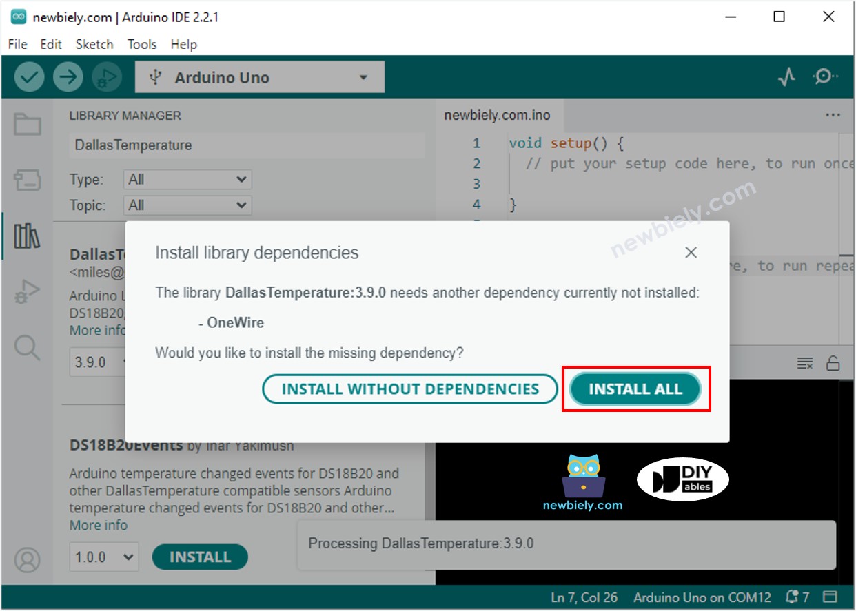
- You will be asked to install the dependency. Click Install All button to install OneWire library.
- Copy the code above and open it with the Arduino IDE.
- Click the Upload button in the Arduino IDE to compile and upload the code to the ESP8266.
- Change the temperature of the environment around the sensor.
- Check out the temperature of the heating element and the room.
Advanced Knowledge
The above mentioned technique is the on-off controller, which is also referred to as a signaller or "bang-bang" controller. It is very easy to implement this method.
An alternative approach known as the PID controller exists. This method of temperature control is more stable, but complex and challenging to comprehend and put into practice. As a result, the PID controller is not widely used.