ESP8266 - GPS
This tutorial instructs you how to use ESP8266 with a NEO-6M GPS module. In detail, we will learn:
- How to connect ESP8266 to a NEO-6M GPS module
- How to program ESP8266 to read GPS coordinates (longitude, latitude, and altitude) from a NEO-6M GPS module
- How to program ESP8266 to calculate the distance from the current GPS position to a predefined GPS coordinate (e.g. coordinates of London).
Apart from longitude, latitude, and altitude, ESP8266 is also able to read GPS speed (km/h), and date time from a NEO-6M GPS module.
Hardware Preparation
Or you can buy the following kits:
| 1 | × | DIYables Sensor Kit (18 sensors/displays) |
Disclosure: Some of the links provided in this section are Amazon affiliate links. We may receive a commission for any purchases made through these links at no additional cost to you.
Additionally, some of these links are for products from our own brand, DIYables .
Additionally, some of these links are for products from our own brand, DIYables .
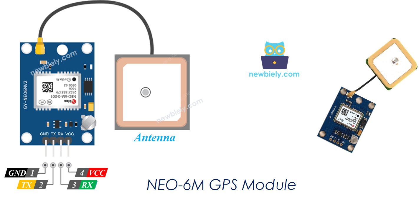
Overview of NEO-6M GPS module
NEO-6M GPS module is a GPS module that can provide the following information:
- Longitude
- Latitude
- Altitude
- GPS speed (km/h)
- Date time
The NEO-6M GPS Module Pinout
The NEO-6M GPS module has 4 pins:
- VCC pin: This should be connected to VCC (5V)
- GND pin: This should be connected to GND (0V)
- TX pin: This is for serial communication and should be connected to the Serial (or SoftwareSerial) RX pin on ESP8266.
- RX pin: This is for serial communication and should be connected to the Serial (or SoftwareSerial) TX pin on ESP8266.
Wiring Diagram
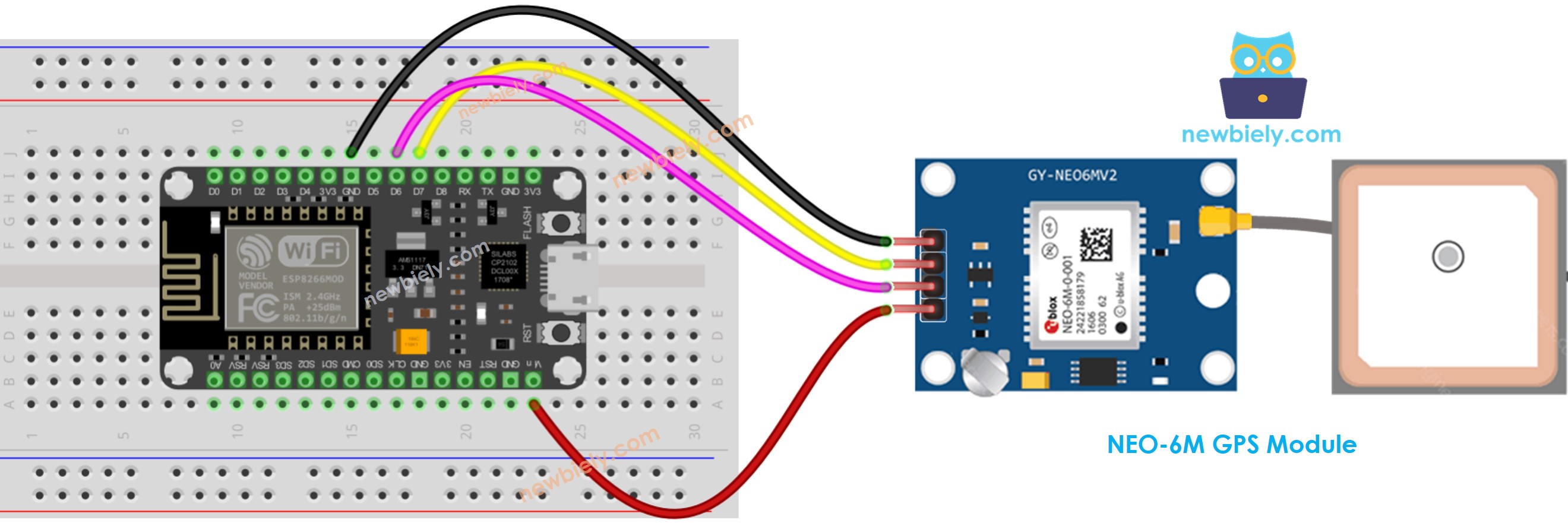
This image is created using Fritzing. Click to enlarge image
See more in ESP8266's pinout and how to supply power to the ESP8266 and other components.
ESP8266 Code
Reading GPS coordinates, speed (km/h), and date time
/*
* This ESP8266 NodeMCU code was developed by newbiely.com
*
* This ESP8266 NodeMCU code is made available for public use without any restriction
*
* For comprehensive instructions and wiring diagrams, please visit:
* https://newbiely.com/tutorials/esp8266/esp8266-gps
*/
#include <TinyGPS++.h>
#include <SoftwareSerial.h>
const int RX_PIN = 3, TX_PIN = 4;
const uint32_t GPS_BAUD = 9600; //Default baud of NEO-6M is 9600
TinyGPSPlus gps; // The TinyGPS++ object
SoftwareSerial gpsSerial(RX_PIN, TX_PIN); // The serial interface to the GPS device
void setup() {
Serial.begin(9600);
gpsSerial.begin(GPS_BAUD);
Serial.println(F("ESP8266 - GPS module"));
}
void loop() {
if (gpsSerial.available() > 0) {
if (gps.encode(gpsSerial.read())) {
if (gps.location.isValid()) {
Serial.print(F("- latitude: "));
Serial.println(gps.location.lat());
Serial.print(F("- longitude: "));
Serial.println(gps.location.lng());
Serial.print(F("- altitude: "));
if (gps.altitude.isValid())
Serial.println(gps.altitude.meters());
else
Serial.println(F("INVALID"));
} else {
Serial.println(F("- location: INVALID"));
}
Serial.print(F("- speed: "));
if (gps.speed.isValid()) {
Serial.print(gps.speed.kmph());
Serial.println(F(" km/h"));
} else {
Serial.println(F("INVALID"));
}
Serial.print(F("- GPS date&time: "));
if (gps.date.isValid() && gps.time.isValid()) {
Serial.print(gps.date.year());
Serial.print(F("-"));
Serial.print(gps.date.month());
Serial.print(F("-"));
Serial.print(gps.date.day());
Serial.print(F(" "));
Serial.print(gps.time.hour());
Serial.print(F(":"));
Serial.print(gps.time.minute());
Serial.print(F(":"));
Serial.println(gps.time.second());
} else {
Serial.println(F("INVALID"));
}
Serial.println();
}
}
if (millis() > 5000 && gps.charsProcessed() < 10)
Serial.println(F("No GPS data received: check wiring"));
}
Detailed Instructions
To get started with ESP8266 on Arduino IDE, follow these steps:
- Check out the how to setup environment for ESP8266 on Arduino IDE tutorial if this is your first time using ESP8266.
- Wire the components as shown in the diagram.
- Connect the ESP8266 board to your computer using a USB cable.
- Open Arduino IDE on your computer.
- Choose the correct ESP8266 board, such as (e.g. NodeMCU 1.0 (ESP-12E Module)), and its respective COM port.
- Launch Arduino IDE
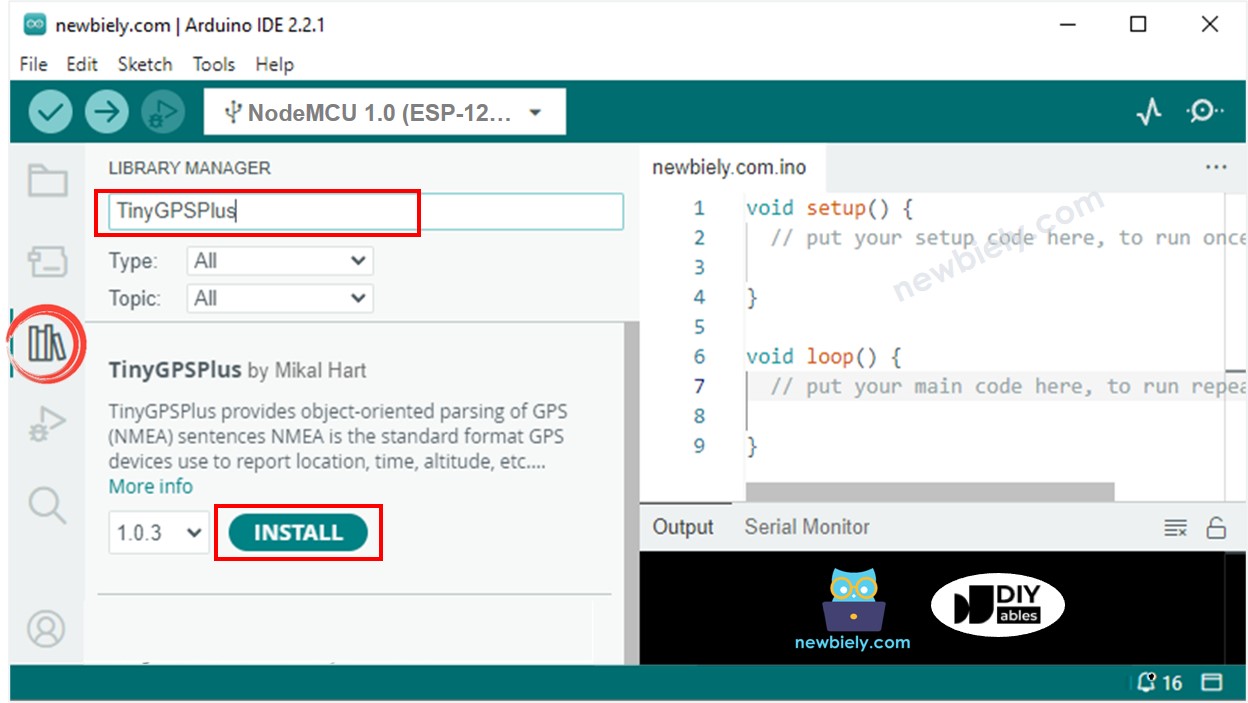
- Click to the Libraries icon on the left bar of the Arduino IDE.
- Search “TinyGPSPlus”, then find the TinyGPSPlus library by Mikal Hart
- Click Install button to install TinyGPSPlus library.
- Copy the code given and open it in the Arduino IDE.
- Click the Upload button in the Arduino IDE to send the code to the ESP8266.
- Check out the result on the Serial Monitor.
8
Serial.println("Hello World!");
Message (Enter to send message to 'Nodemcu 1.0 (ESP-12E Module)' on 'COM15')
New Line
9600 baud
Calculating the distance from current location to a predefined location
This code computes the distance between the present location and London (latitude: 51.508131, longitude: -0.128002).
/*
* This ESP8266 NodeMCU code was developed by newbiely.com
*
* This ESP8266 NodeMCU code is made available for public use without any restriction
*
* For comprehensive instructions and wiring diagrams, please visit:
* https://newbiely.com/tutorials/esp8266/esp8266-gps
*/
#include <TinyGPS++.h>
#include <SoftwareSerial.h>
const int RX_PIN = 3, TX_PIN = 4;
const uint32_t GPS_BAUD = 9600; //Default baud of NEO-6M is 9600
TinyGPSPlus gps; // The TinyGPS++ object
SoftwareSerial gpsSerial(RX_PIN, TX_PIN); // The serial interface to the GPS device
const double LONDON_LAT = 51.508131;
const double LONDON_LON = -0.128002;
void setup() {
Serial.begin(9600);
gpsSerial.begin(GPS_BAUD);
Serial.println(F("ESP8266 - GPS module"));
}
void loop() {
if (gpsSerial.available() > 0) {
if (gps.encode(gpsSerial.read())) {
if (gps.location.isValid()) {
double latitude = gps.location.lat();
double longitude = gps.location.lng();
unsigned long distanceKm = TinyGPSPlus::distanceBetween(latitude, longitude, LONDON_LAT, LONDON_LON) / 1000;
Serial.print(F("- latitude: "));
Serial.println(latitude);
Serial.print(F("- longitude: "));
Serial.println(longitude);
Serial.print(F("- distance to London: "));
Serial.println(distanceKm);
} else {
Serial.println(F("- location: INVALID"));
}
Serial.println();
}
}
if (millis() > 5000 && gps.charsProcessed() < 10)
Serial.println(F("No GPS data received: check wiring"));
}
Detailed Instructions
- Wire the components as shown in the diagram.
- Connect the ESP8266 board to your computer using a USB cable.
- Open Arduino IDE on your computer.
- Choose the correct ESP8266 board, such as (e.g. NodeMCU 1.0 (ESP-12E Module)), and its respective COM port.
- Copy the code and open it in the Arduino IDE.
- Click the Upload button in the Arduino IDE to send the code to the ESP8266.
- Check out the result on the Serial Monitor.
8
Serial.println("Hello World!");
Message (Enter to send message to 'Nodemcu 1.0 (ESP-12E Module)' on 'COM15')
New Line
9600 baud