ESP8266 - LED RGB
This tutorial instructs you how to use ESP8266 to control RGB LED. In detail, we will learn:
- How RGB LED works.
- How to connect an RGB LED to a ESP8266.
- How to program the ESP8266 to control the color of the RGB LED.
Hardware Preparation
Or you can buy the following kits:
| 1 | × | DIYables Sensor Kit (18 sensors/displays) |
Additionally, some of these links are for products from our own brand, DIYables .
Overview of RGB LED
The RGB LED can produce any color by combining the three primary colors of red, green, and blue. It is composed of three distinct LEDs( red, green, and blue), but all contained in a single housing.
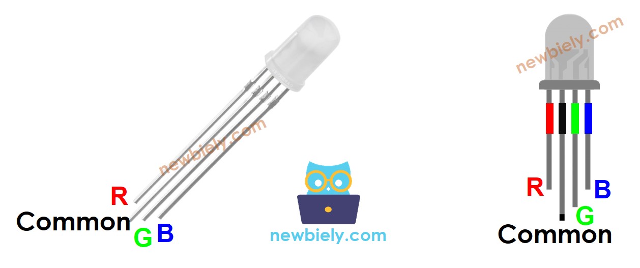
The RGB LED Pinout
An RGB LED has four pins:
- The common (cathode-) pin needs to be linked to GND (0V)
- The R (red) pin is used to regulate red
- The G (green) pin is used to regulate green
- The B (blue) pin is used to regulate blue
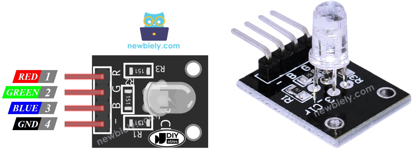
To make an RGB LED work with ESP8266, we gotta add current-limiting resistors. That can make the wiring a bit complicated. But hey, there's a solution! We can use an RGB LED module that already has resistors built-in. Easy peasy!
RGB LED Module also includes four pins:
- Common (Cathode-) pin: needs to be connected to GND (0V)
- R (red): pin is used to control red
- G (green): pin is used to control green
- B (blue): pin is used to control blue
※ NOTE THAT:
The common pin that can be either a cathode or anode can vary depending on the type of RGB LED. This tutorial will use a common cathode pin.
How it works
In the realm of physics, three color values make up a color: Red (R), Green (G), and Blue (B). Each value ranges from 0 to 255. The combination of three values produces a total of 256 x 256 x 256 colors.
We can set the RGB LED to any color we desire by using ESP8266 to generate PWM signals (ranging from 0 to 255) to the R, G, and B pins. The duty cycle of PWM signals sent to the R, G and B pins are in proportion to the color values of Red, Green and Blue respectively.
Wiring Diagram
- Wiring diagram between ESP8266 and RGB LED
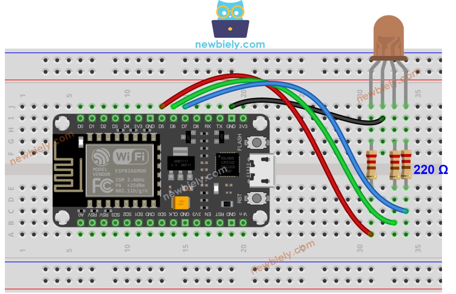
This image is created using Fritzing. Click to enlarge image
- Wiring diagram between ESP8266 and RGB LED module
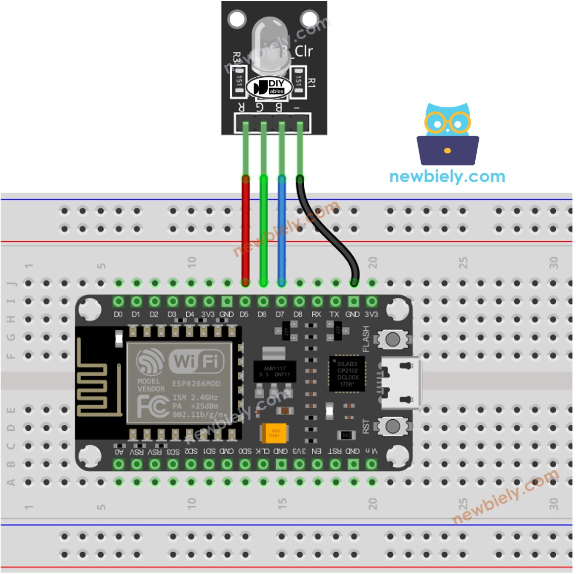
This image is created using Fritzing. Click to enlarge image
See more in ESP8266's pinout and how to supply power to the ESP8266 and other components.
How To Control RGB LED
Let's learn how to control the GRB LED to any color, for example #00979D step-by-step:
- First, determine which color you want to display and get its color code. Tips:
- You can pick up the desired color code from the color picker
- If you want to use a color in an image, use the online Colors From Image tool
- Then, convert the color code to R, G, B values using the tool from w3school. Take note of these values. In this case: R = 0, G = 151, B = 157

- Specify the ESP8266 pins that link to the R, G, and B pins. For instance:
- Set the following ESP8266 pins to output mode:
- Control LED to emit the color of #00979D, which is composed of Red = 0, Green = 151, and Blue = 157.
ESP8266 - RGB LED Example Code
The ESP8266 code below changes the color of the LED in a sequence of:
- #00C9CC (Red = 0, Green = 201, Blue = 204)
- #F7788A (Red = 247, Green = 120, Blue = 138)
- #34A853 (Red = 52, Green = 168, Blue = 83)
When using many colors, we could shorten the ESP8266 code by creating a function:
Addtional Knowledge
For RGB LED with common Anode, you need to:
- Connect the common pin to 3.3V of ESP8266.
- Invert the R, G and B values in analogWrite() function, i.e. use 255 - R, 255 - G, and 255 - B, respectively
A sequence of RGB LEDs connected together forms an RGB LED Strip. LED strips can be divided into addressable LED strips and non-addressable LED strips. We will create tutorials for both types of LED strips.
※ NOTE THAT:
Do not use a single resistor in the common pin of an RGB LED instead of three resistors in the other pins.
This is because, although in theory it is ok to use a single resistor in the common pin, in reality this is not the case. The LEDs in an RGB package are not identical, meaning that their resistors are different. As a result, the current is distributed unequally to each LED, causing the brightness to be unequal, which can lead to the destruction of one or more of the LEDs, and eventually the other LEDs.