ESP8266 - LCD
This tutorial instructs you how to use LCD display with ESP8266, how to program for ESP8266 to display text, special characters on LCD.
Hardware Preparation
Or you can buy the following kits:
| 1 | × | DIYables Sensor Kit (18 sensors/displays) |
Additionally, some of these links are for products from our own brand, DIYables .
Buy Note: Alternatively, you can assemble the LCD I2C display using LCD 1602 Display and PCF8574 I2C Adapter Module.
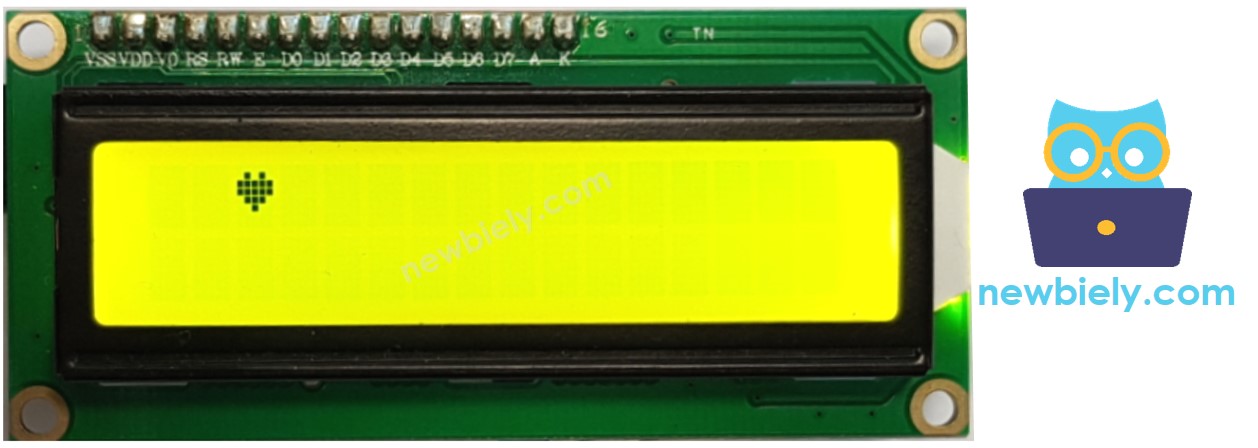
Overview of LCD I2C 16x2
The LCD I2C is a better alternative for the standard LCD. With only 4 pins, It makes it easy to connnect to ESP8266. A built-in potentiometer makes it easy to adjust the contrast of LCD.
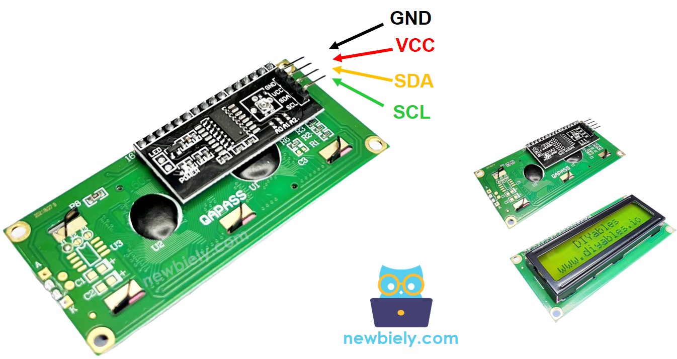
The LCD I2C Pinout
The LCD I2C uses an I2C interface to connect to ESP8266. It has 4 pins:
- GND pin: This should be connected to GND (0V).
- VCC pin: This is the power supply for the LCD and should be connected to VCC (5V).
- SDA pin: This is the I2C data signal.
- SCL pin: This is the I2C clock signal.
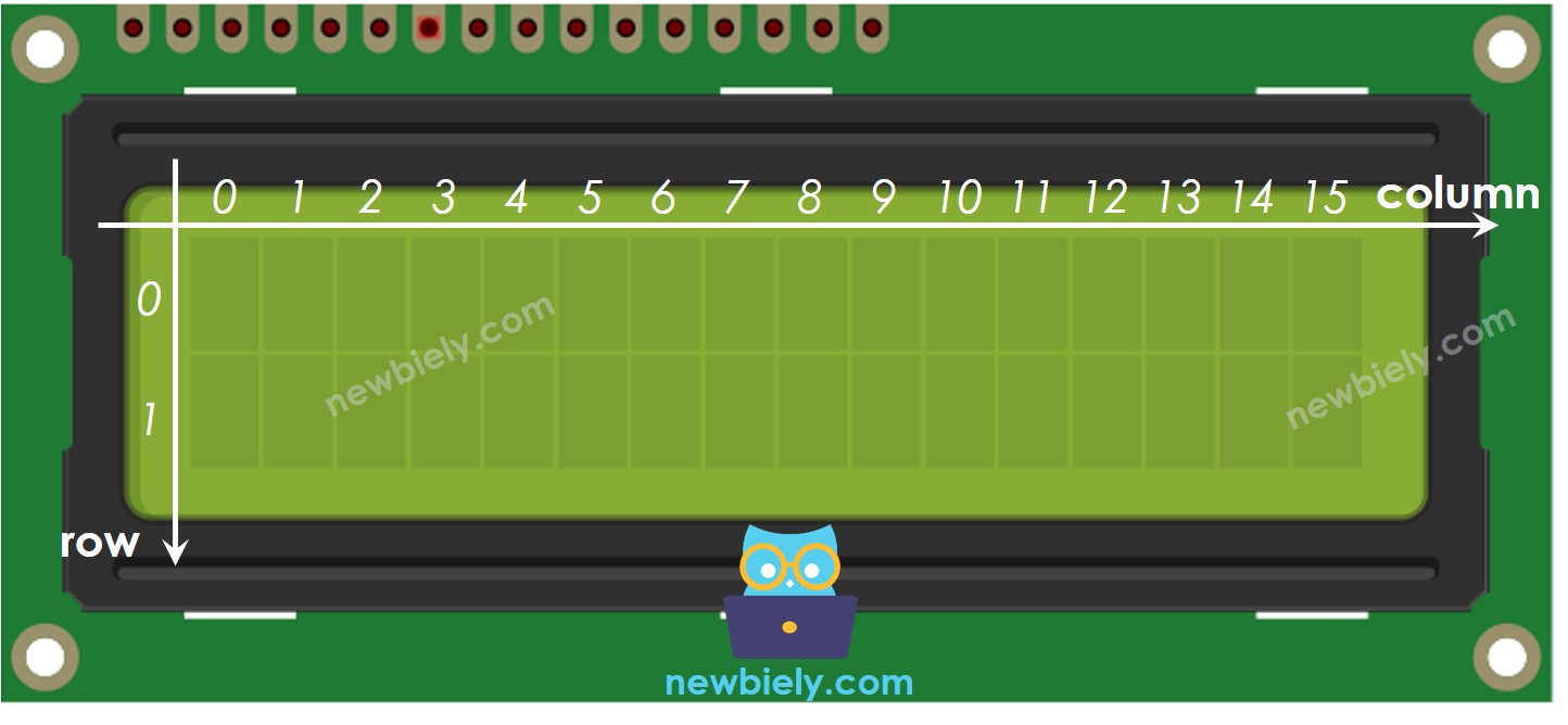
LCD Coordinate
The LCD I2C 16x2 has a total of 16 columns and 2 rows. The columns and rows are numbered starting from 0.
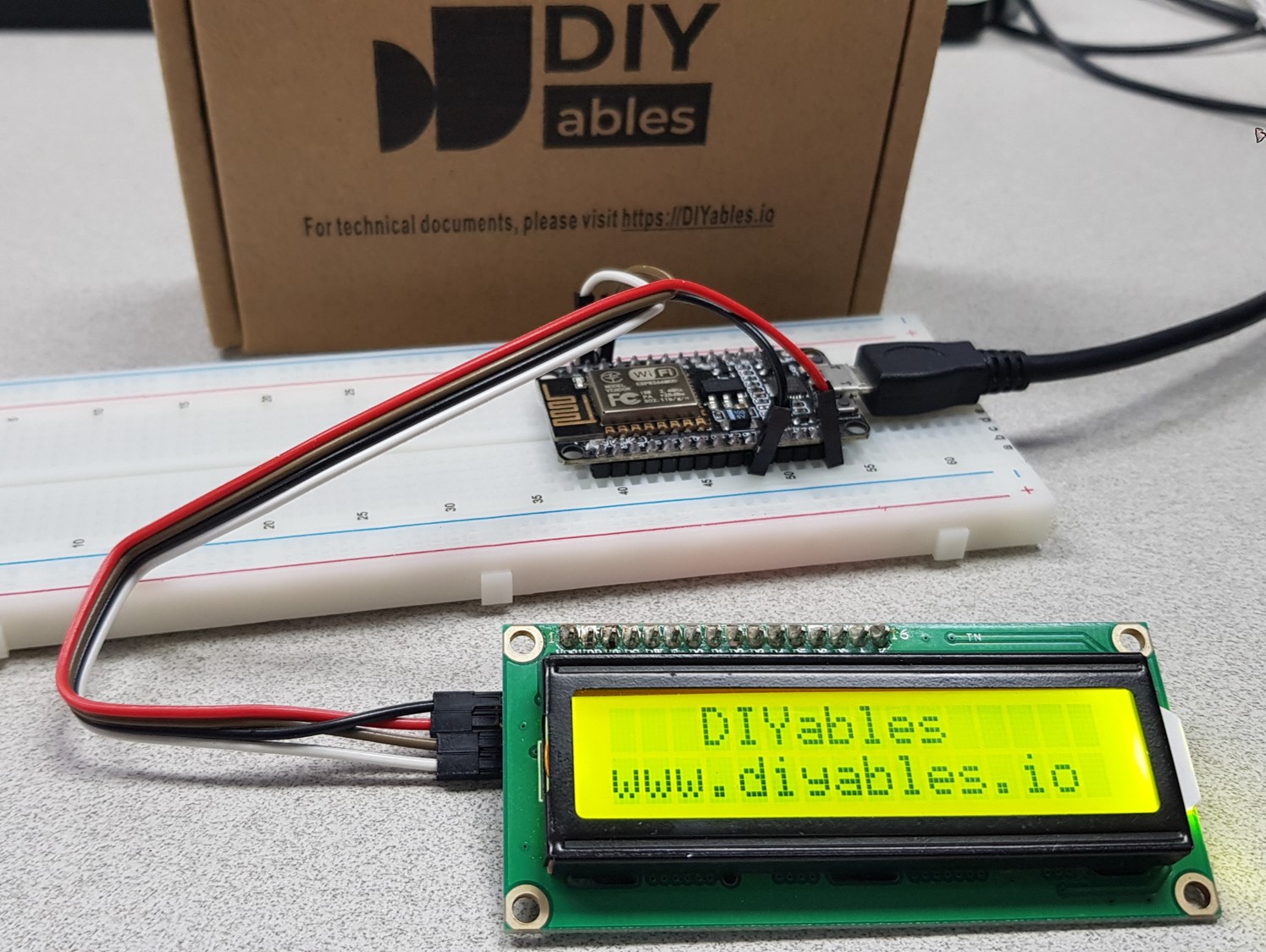
Wiring Diagram
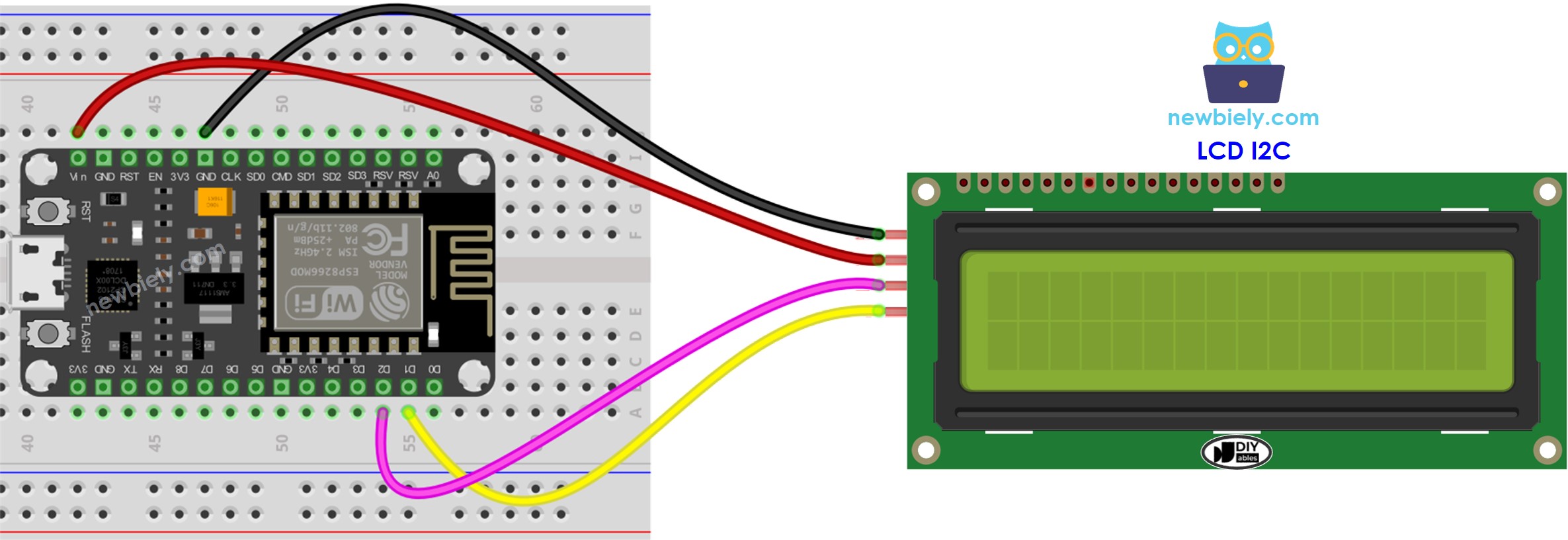
This image is created using Fritzing. Click to enlarge image
See more in ESP8266's pinout and how to supply power to the ESP8266 and other components.
| LCD I2C | ESP8266 |
|---|---|
| Vin | Vin |
| GND | GND |
| SDA | D2 (GPIO4) |
| SCL | D1 (GPIO5) |
How To Program For LCD I2C
The DIYables_LCD_I2C library needs to be included in order to use the LCD.
- Setup the LCD:
The LCD must be set up before it can be used.
- Write to the LCD:
Writing to the LCD is made simple due to the DIYables_LCD_I2C library.
- Declare an object of the DIYables_LCD_I2C class, specifying its I2C address, number of columns, and number of rows.
- Begin the LCD.
- Place the cursor at the desired location (column_index, row_index)
- Display a message on the LCD screen.
Explore the possibilities of what can be accomplished with LCD by looking at the "Do More with LCD" section.
※ NOTE THAT:
The address of the LCD may differ depending on the manufacturer. In our code, we have used 0x27, which is specified by the DIYables manufacturer.
ESP8266 Code
Detailed Instructions
To get started with ESP8266 on Arduino IDE, follow these steps:
- Check out the how to setup environment for ESP8266 on Arduino IDE tutorial if this is your first time using ESP8266.
- Wire the components as shown in the diagram.
- Connect the ESP8266 board to your computer using a USB cable.
- Open Arduino IDE on your computer.
- Choose the correct ESP8266 board, such as (e.g. NodeMCU 1.0 (ESP-12E Module)), and its respective COM port.
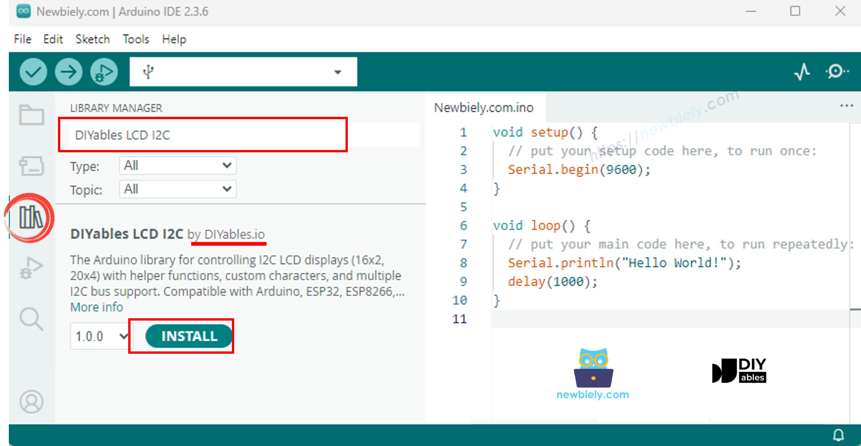
- Click to the Libraries icon on the left bar of the Arduino IDE.
- Search for "DIYables LCD I2C" and locate the DIYables_LCD_I2C library created by DIYables.
- Then, click the Install button to add the library.
- Copy the code and open it in the Arduino IDE.
- Click the Upload button in the Arduino IDE to compile and upload the code to the ESP8266.
- Check out the outcome on the LCD.
- Of images
- Experiment with changing the words and the placement of pictures.
Video Tutorial
Do More with LCD
Custom Character
lcd.print() only allows ASCII characters. To show a special character or symbol (e.g. heart, angry bird), use the character generator.
An LCD 16x2 has the capacity to show 32 characters. Each character is made up of 40 pixels, with 8 rows and 5 columns.
The character generator produces a character that is 40 pixels in size. To use it, simply follow these steps:
The outcome displayed on the LCD screen is: . The result shown on the LCD is:
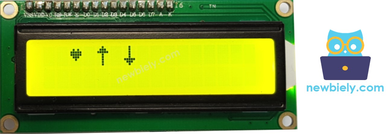
Multiple custom characters
We can make a maximum of 8 custom characters, numbered from 0 to 7. The following example creates and shows three of them.
The outcome displayed on the LCD is: . The result shown on the LCD is:
Summary: how to use custom character on LCD
- Utilize the character generator to generate binary code for your custom character.
- Copy the binary code generated from the previous step and declare it.
- Define a character of your own design in the setup() routine and assign it a numerical value between 0 and 7.
- Display the custom character on the LCD at any time, either in the setup() or loop() function.
Other functions
- Print "Hello World"
Insert the following functions into the loop() function in succession:
- Clear the LCD screen
- Delay for 5000 milliseconds
- Print "Hello World"
- Position the cursor at the top left corner of the LCD.
- Position the cursor at a particular column and row.
- Show the cursor on the LCD screen.
- Makes the LCD cursor invisible.
- Show the LCD cursor blinking.
- Disable the blinking of the LCD cursor.
- Additionally, you can find information at LiquidCrystal Library Reference
Challenge Yourself
Utilize LCD to accomplish one of the following projects:
- Transmit text from PC (through Serial Monitor) and show it on LCD. Tip: Look at How to send data from PC to Aduino
- Demonstrate the pressed key of the keypad on LCD. Tip: Look at ESP8266 - Keypad
Troubleshooting on LCD I2C
- Adjust the contrast of LCD by turning the potentiometer located on the back of the LCD.
- Depending on the manufacturer, the I2C address of the LCD may vary. Generally, the default I2C address of the LCD is either 0x27 or 0x3F. Try these values one at a time. If unsuccessful, run the code below to determine the I2C address.
The output displayed on the Serial Monitor is: . The effect that can be seen on the Serial Monitor is: . What appears on the Serial Monitor is: