ESP8266 - LCD 20x4
This tutorial instructs you how to use LCD 20x4 display with ESP8266, how to program for ESP8266 to display text on LCD 20x4.
Hardware Preparation
| 1 | × | ESP8266 NodeMCU | |
| 1 | × | USB A to Mini-B USB cable | |
| 1 | × | LCD 20x4 | |
| 1 | × | Jumper Wires | |
| 1 | × | Breadboard | |
| 1 | × | Recommended: Screw Terminal Expansion Board for ESP8266 | |
| 1 | × | Recommended: Power Splitter for ESP8266 Type-C |
Or you can buy the following kits:
| 1 | × | DIYables Sensor Kit (30 sensors/displays) | |
| 1 | × | DIYables Sensor Kit (18 sensors/displays) |
Additionally, some of these links are for products from our own brand, DIYables .
Overview of LCD I2C 20x4
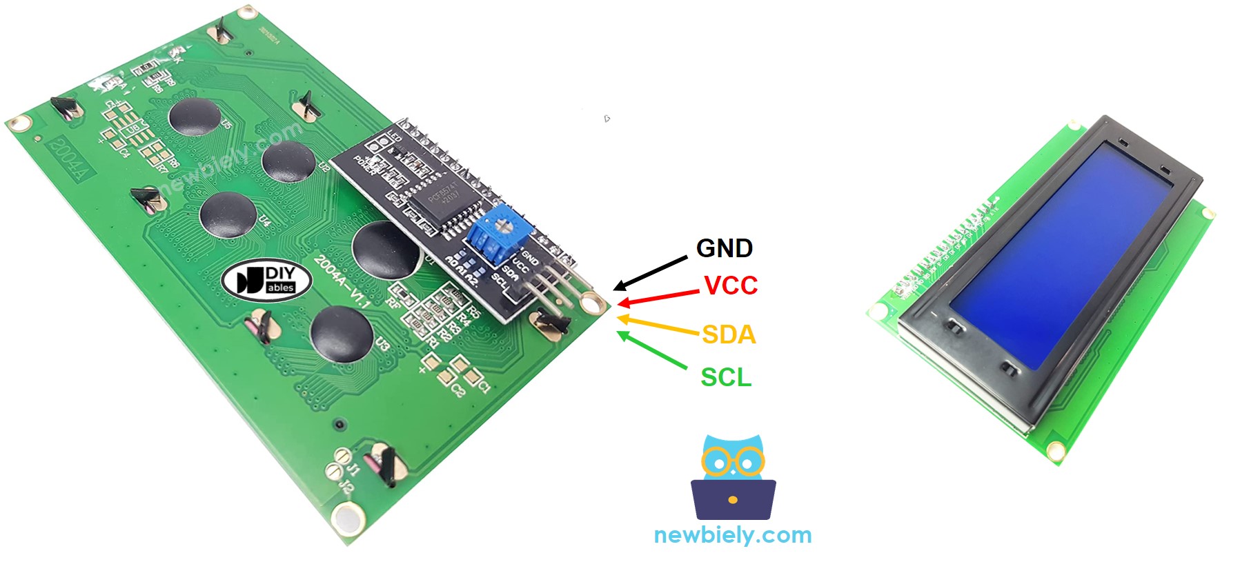
LCD I2C is made up of a standard LCD, an I2C module and a potentiometer.
The LCD Pinout
The LCD I2C uses the I2C interface to connect to ESP8266. It has four pins:
- The GND pin needs to be connected to ground (0V).
- The VCC pin is the power supply for the LCD and must be connected to VCC (5V).
- The SDA pin is the I2C data signal.
- The SCL pin is the I2C clock signal.

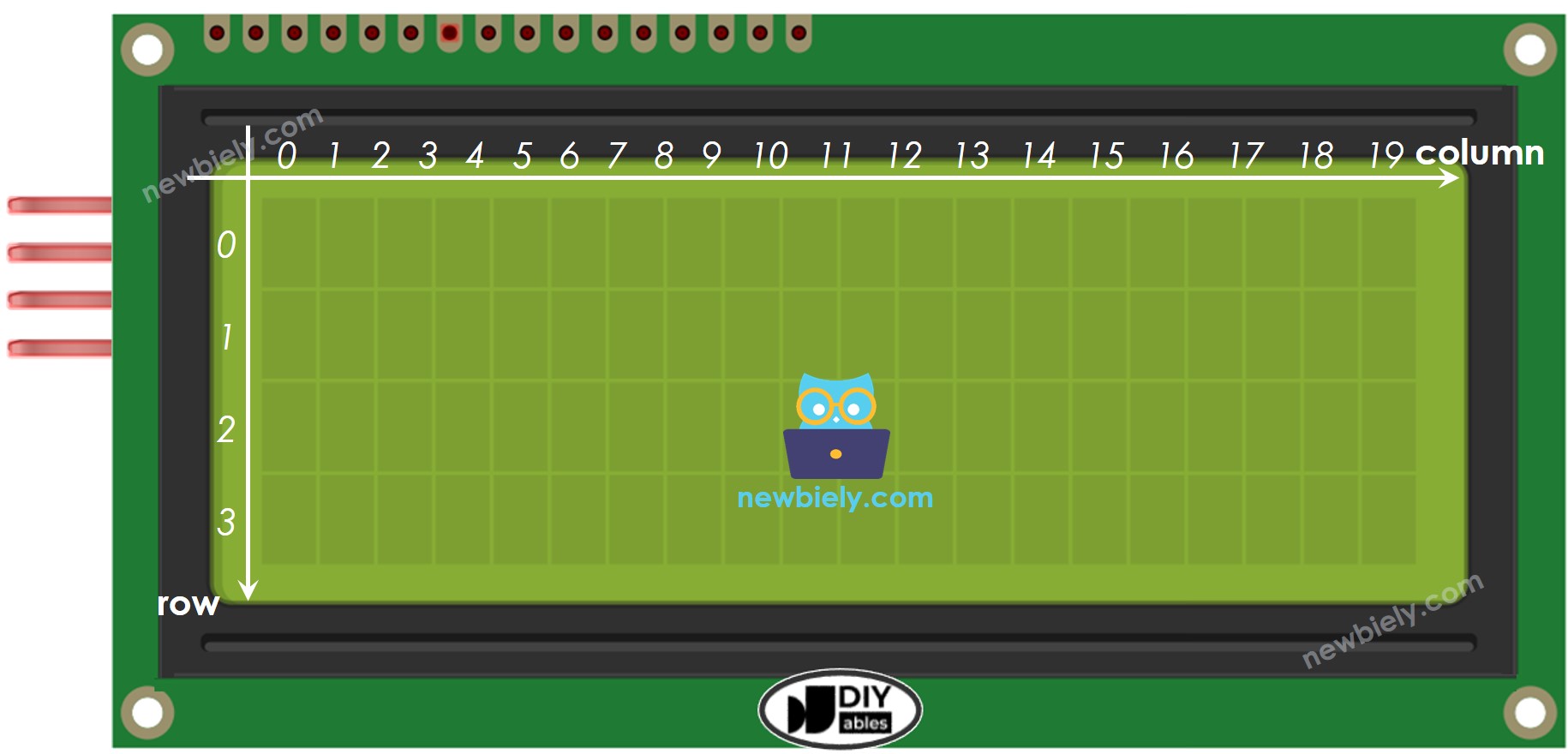
LCD Coordinate
The LCD I2C 20x4 has 16 columns and 2 rows, with the columns and rows being numbered starting from 0.

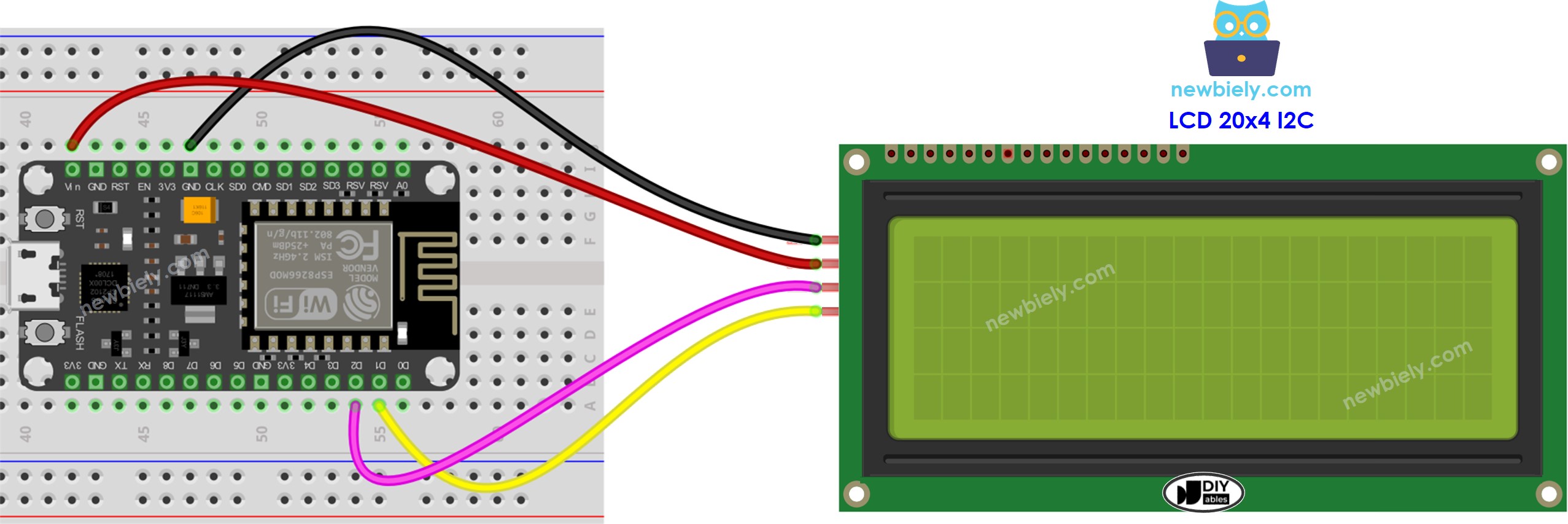
Wiring Diagram

This image is created using Fritzing. Click to enlarge image
See more in ESP8266's pinout and how to supply power to the ESP8266 and other components.
| LCD I2C | ESP8266 |
|---|---|
| Vin | Vin |
| GND | GND |
| SDA | D2 (GPIO4) |
| SCL | D1 (GPIO5) |
How To Program For LCD I2C
The LiquidCrystal_I2C library needs to be included in order to use the LCD.
- Set up the LCD:
The LCD must be set up properly for it to work correctly.
- Write to the LCD:
Writing to the LCD is easy thanks to the LiquidCrystal_I2C library.
- Create a LiquidCrystal_I2C object with an I2C address, the number of columns, and the number of rows specified.
- Start up the LCD.
- Go to the column and row indicated by column_index and row_index respectively.
- Display a message on the LCD.
Explore the possibilities of what can be achieved with LCD by looking at the "Do More with LCD" section.
※ NOTE THAT:
The address of the LCD may differ depending on the manufacturer. For our code, we used 0x27 as specified by DIYables.
ESP8266 Code
Detailed Instructions
To get started with ESP8266 on Arduino IDE, follow these steps:
- Check out the how to setup environment for ESP8266 on Arduino IDE tutorial if this is your first time using ESP8266.
- Wire the components as shown in the diagram.
- Connect the ESP8266 board to your computer using a USB cable.
- Open Arduino IDE on your computer.
- Choose the correct ESP8266 board, such as (e.g. NodeMCU 1.0 (ESP-12E Module)), and its respective COM port.
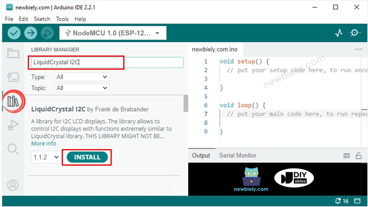
- Click to the Libraries icon on the left bar of the Arduino IDE.
- Search for "LiquidCrystal I2C" and locate the LiquidCrystal_I2C library created by Frank de Brabander.
- Then, click the Install button to add the library.

- Copy the code and open it with the Arduino IDE.
- Click the Upload button in the IDE to send the code to the ESP8266.
- Check the LCD for the result.
- Experiment with altering the text and its location.
