ESP8266 Control LED via Bluetooth
This tutorial instructs you how to program ESP8266 to control a LED through either Bluetooth or BLE.
- To control the LED with Bluetooth, the HC-05 Bluetooth module should be used.
- To control the LED with BLE, the HM-10 BLE module should be used.
This tutorial gives guidance on how to use both modules.
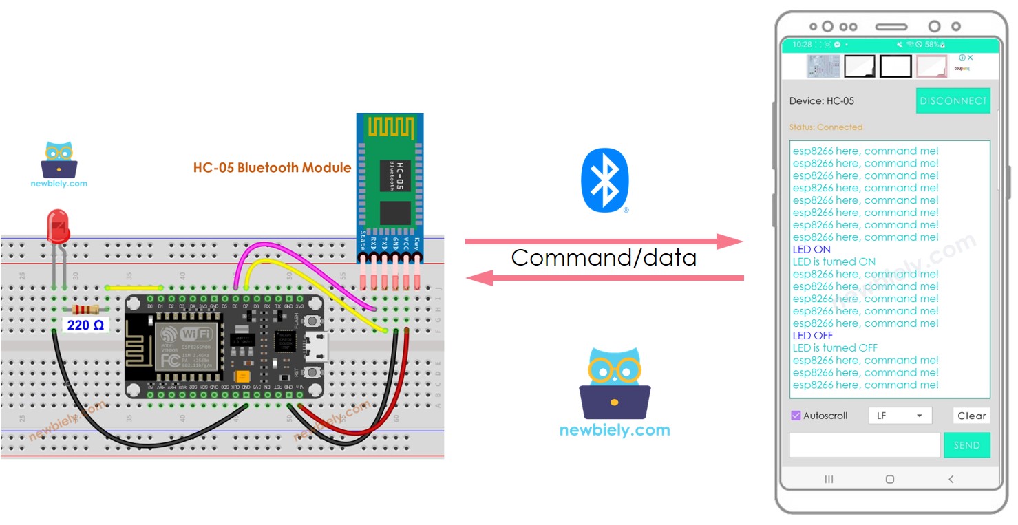
We will use the Bluetooth Serial Monitor App on a smartphone to send commands to ESP8266.
These commands include:
- LED ON: to switch on the LED
- LED OFF: to switch off the LED
Hardware Preparation
Or you can buy the following kits:
| 1 | × | DIYables Sensor Kit (18 sensors/displays) |
Additionally, some of these links are for products from our own brand, DIYables .
Buy Note: Use the LED Module for easier wiring. It includes an integrated resistor.
Overview of LED and Bluetooth Module
If you are unfamiliar with LED and Bluetooth Module (including pinout, functionality, and programming), the following tutorials can help:
Wiring Diagram
- If you desire to manipulate an LED through Bluetooth, the HC-05 Bluetooth module should be used with the wiring diagram provided below.
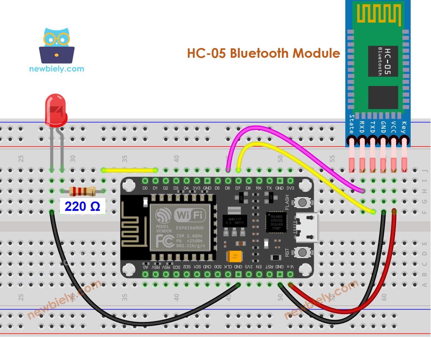
This image is created using Fritzing. Click to enlarge image
- If you desire to manipulate LED through BLE, the HM-10 BLE module should be used with the wiring diagram provided below.
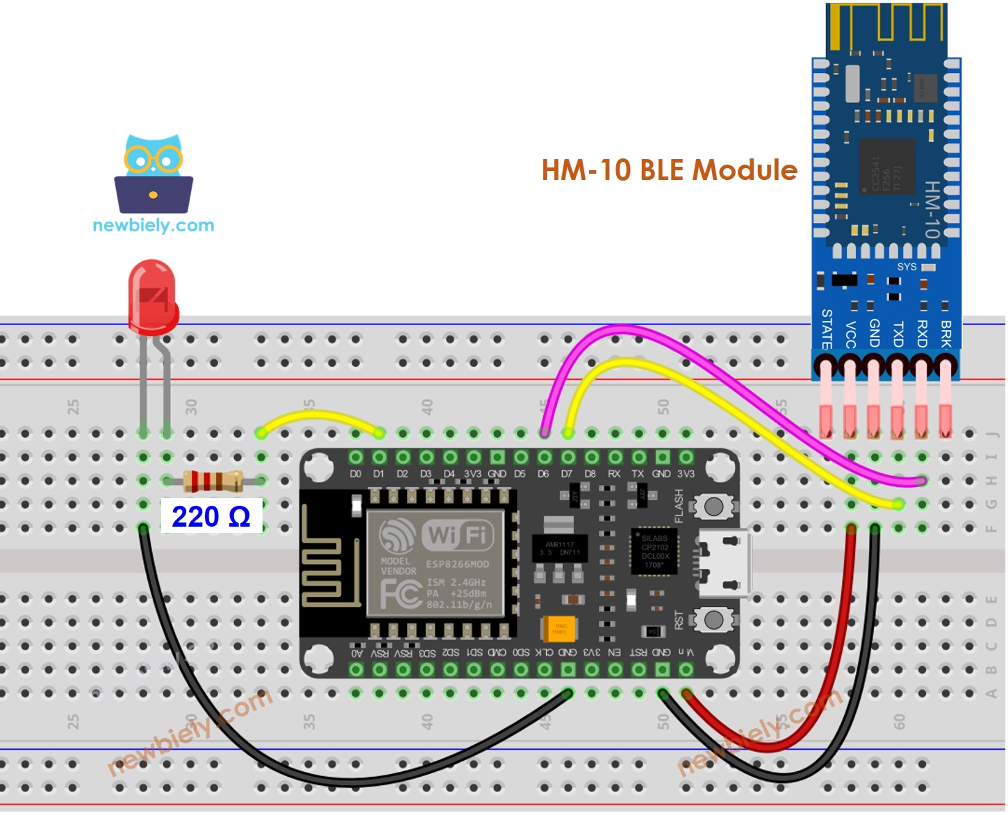
This image is created using Fritzing. Click to enlarge image
See more in ESP8266's pinout and how to supply power to the ESP8266 and other components.
ESP8266 Code - controls LED via Bluetooth/BLE
The code functions for both the HC-10 Bluetooth module and the HM-10 BLE module. It is applicable to both.
Detailed Instructions
To get started with ESP8266 on Arduino IDE, follow these steps:
- Check out the how to setup environment for ESP8266 on Arduino IDE tutorial if this is your first time using ESP8266.
- Wire the components as shown in the diagram.
- Connect the ESP8266 board to your computer using a USB cable.
- Open Arduino IDE on your computer.
- Choose the correct ESP8266 board, such as (e.g. NodeMCU 1.0 (ESP-12E Module)), and its respective COM port.
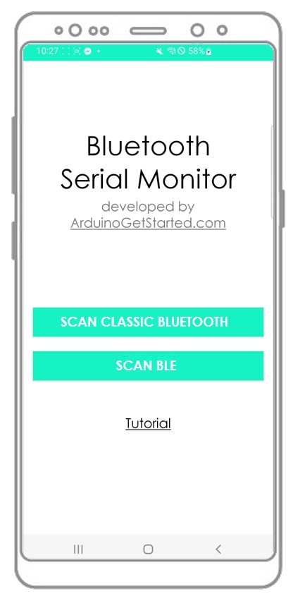
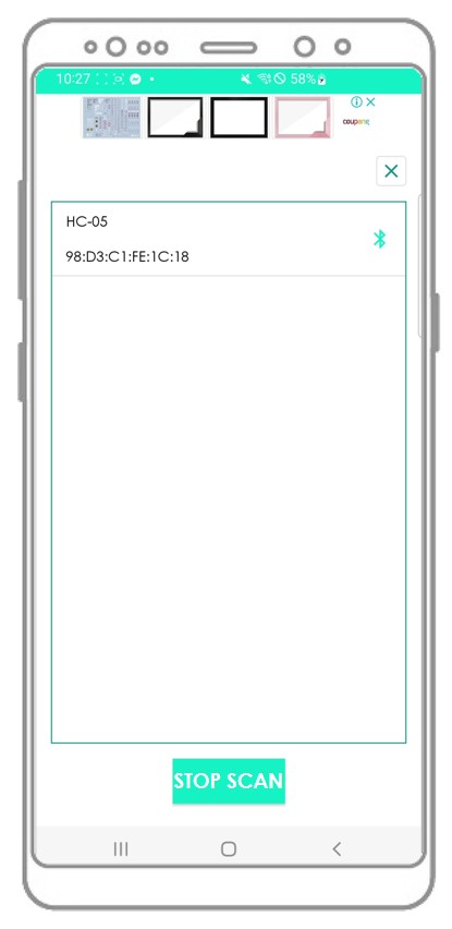
- Download and install the Bluetooth Serial Monitor App on your smartphone.
- Copy the code and open it with the Arduino IDE. Then, click the Upload button to upload the code to the ESP8266. If you experience any difficulty uploading the code, try disconnecting the TX and RX pins from the Bluetooth module, uploading the code, and then reconnecting the RX/TX pins again.
- Once the code is uploaded, open the Bluetooth Serial Monitor App on your smartphone and select either Classic Bluetooth or BLE, depending on the module you used.
- Connect the Bluetooth App to the HC-05 Bluetooth module or HM-10 BLE module.
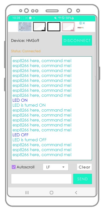
- Enter either “LED ON” or “LED OFF” and press the Send button
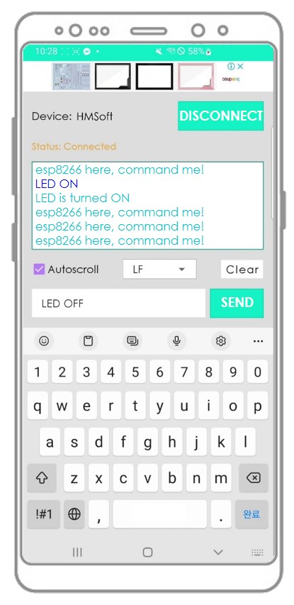
- Check the LED's state on the ESP8266 board. It will be either ON or OFF.
- We can also view the LED's state on the Bluetooth App.
- Check out the outcome on the Android App.
You may ponder how ESP8266 can comprehend an entire command? For example, when we transmit the “OFF” directive, how can ESP8266 recognize whether the command is “O”, “OF” or “OFF”?
When sending a command, The bluetooth App adds a newline character ('\n') by choosing “newline” option on the App. ESP8266 reads data until it encounters the newline character. The newline character serves as a command separator.
If you find the Bluetooth Serial Monitor app helpful, please rate it 5 stars on Play Store. Your appreciation is much appreciated!