ESP8266 - Door Sensor - Relay
This tutorial instructs you how to use the ESP8266 and door sensor to control the relay. By connecting the relay to a soleniod lock, light bulb, LED strip, motor, or actuator..., we can use a door sensor to control the them. We will learn two different applications:
Application 1 - The relay is activated when door is open and the relay is deactivated when door is closed. The relay state is synchronized with the door sensor state. In detail:
- ESP8266 turns on the relay when the door is opened.
- ESP8266 turns off the relay when the door is closed.
Application 2 - The relay state is toggled each time the door is opened. More specifically:
- If ESP8266 detects that the door has been opened (the sensor state changes from LOW to HIGH), it will turn ON the relay if it's currently OFF, or turn OFF the relay if it's currently ON.
- Closing the door sensor does not affect to the relay state.
Hardware Preparation
Or you can buy the following kits:
| 1 | × | DIYables Sensor Kit (30 sensors/displays) | |
| 1 | × | DIYables Sensor Kit (18 sensors/displays) |
Additionally, some of these links are for products from our own brand, DIYables .
Overview of Relay and Door Sensor
If you are unfamiliar with relay and door sensor (including pinout, operation, and programming), the following tutorials can help:
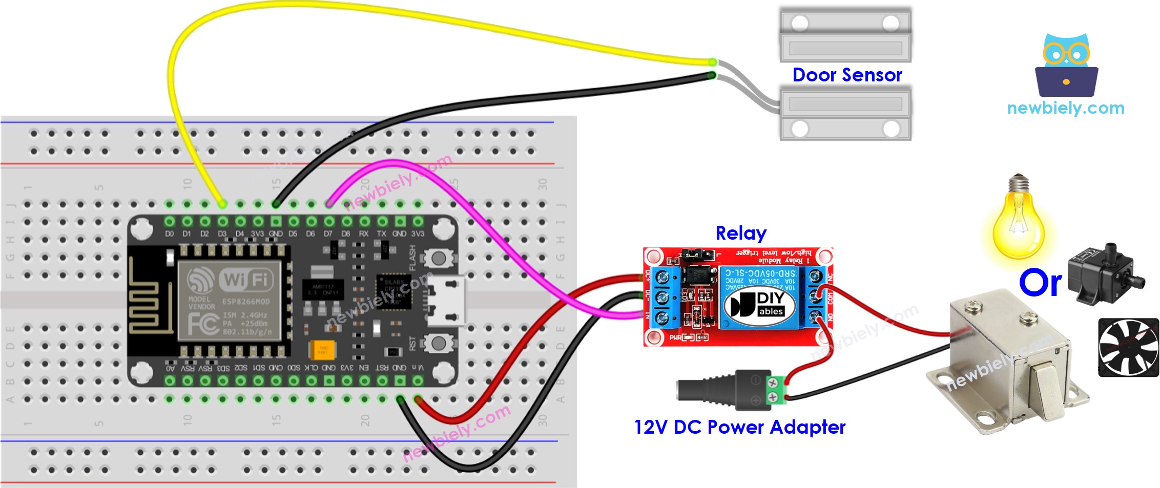
Wiring Diagram

This image is created using Fritzing. Click to enlarge image
See more in ESP8266's pinout and how to supply power to the ESP8266 and other components.
Application 1 - The relay state is in sync with the door sensor state
ESP8266 Code
Detailed Instructions
To get started with ESP8266 on Arduino IDE, follow these steps:
- Check out the how to setup environment for ESP8266 on Arduino IDE tutorial if this is your first time using ESP8266.
- Wire the components as shown in the diagram.
- Connect the ESP8266 board to your computer using a USB cable.
- Open Arduino IDE on your computer.
- Choose the correct ESP8266 board, such as (e.g. NodeMCU 1.0 (ESP-12E Module)), and its respective COM port.
- Connect an ESP8266 to your computer with a USB cable.
- Launch the Arduino IDE, and select the correct board and port.
- Copy the code and open it in the Arduino IDE.
- Click the Upload button on the Arduino IDE to compile and upload the code to the ESP8266.

- Open and close the door
- Check out the change in the relay's condition.
You will see that the relay state is in sync with the door sensor state.
Code Explanation
Check out the line-by-line explanation contained in the comments of the source code!
Application 2 - Door Sensor toggles Relay
ESP8266 Code - Door Sensor toggles Relay
Code Explanation
You can locate the explanation in the comment lines of the ESP8266 code above.
In the code, the expression relay_state = !relay_state is equivalent to the following code:
Detailed Instructions
- Copy the code and open it in the Arduino IDE.
- Upload the code to the ESP8266.
- Open and close the door several times.
- Check out the change in the relay's state.
You'll notice that the relay will switch on or off one time whenever you close the door.
