ESP8266 - Servo Motor
This tutorial instructs you how to use ESP8266 to control servo motor. In detail, we will learn:
- How to connect servo motor to ESP8266
- How to program for ESP8266 to control a servo motor
- How to control the speed of a servo motor using ESP8266
Hardware Preparation
Or you can buy the following kits:
| 1 | × | DIYables Sensor Kit (18 sensors/displays) |
Additionally, some of these links are for products from our own brand, DIYables .
Buy Note: For controlling multiple servo motors, use the PCA9685 16 Channel PWM Servo Driver Module to save MCU pins and simplify wiring.
Overview of Servo Motor
A servo motor is a component capable of rotating its shaft (usually within a range of 0 to 180 degrees) to control the angular position of an object.
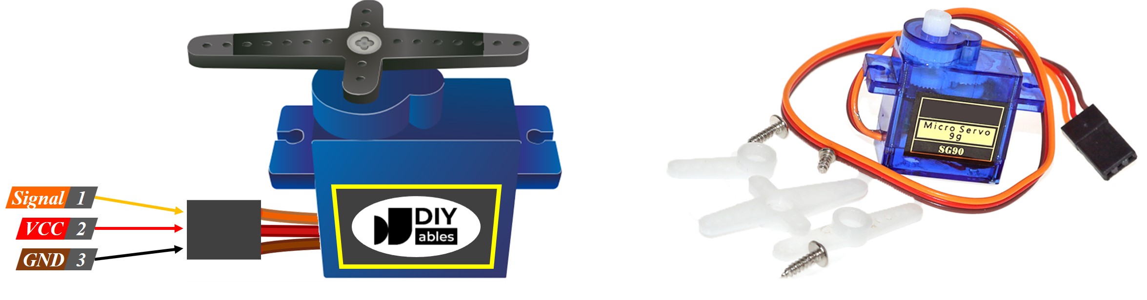
The Servo Motor Pinout
The servo motor has three pins:
- VCC pin (usually red) must be connected to VCC (5V)
- GND pin (usually black or brown) must be connected to GND (0V)
- Signal pin (usually yellow or orange) which receives the PWM control signal from an ESP8266's pin.
ESP8266 - Servo Motor
Some of the ESP8266 pins can be programmed to produce a PWM signal. Connecting the servo motor's signal pin to an ESP8266 pin and programming it to generate PWM on the same pin allows us to control the servo motor.
Thanks to the ESP8266 Servo library, controlling a servo motor is easy. We do not need to understand how the servo motor works or how to generate a PWM signal. All we need to do is learn how to use the library.
Wiring Diagram
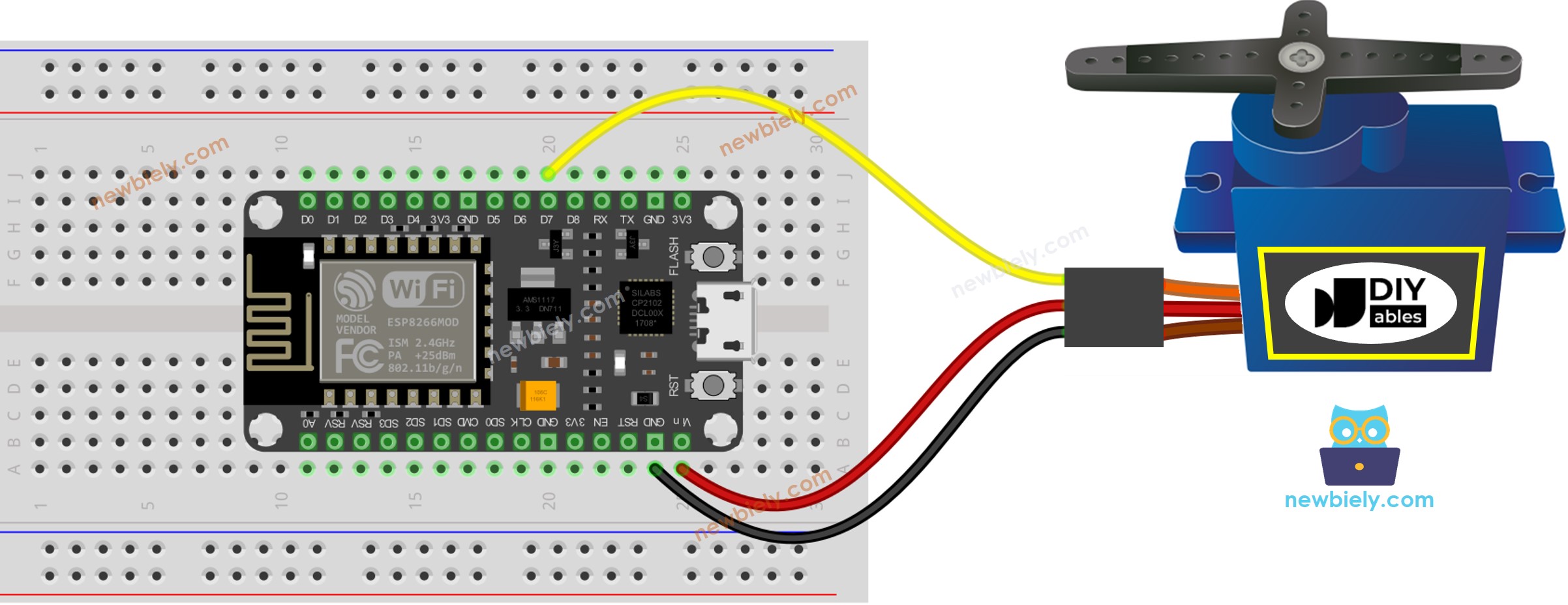
This image is created using Fritzing. Click to enlarge image
For the sake of simplicity, the above wiring diagram is utilized for testing or learning purposes, and for a small-torque servo motor. In actuality, we strongly suggest using an external power supply for the servo motor. The wiring diagram below illustrates how to connect the servo motor to an external power source.
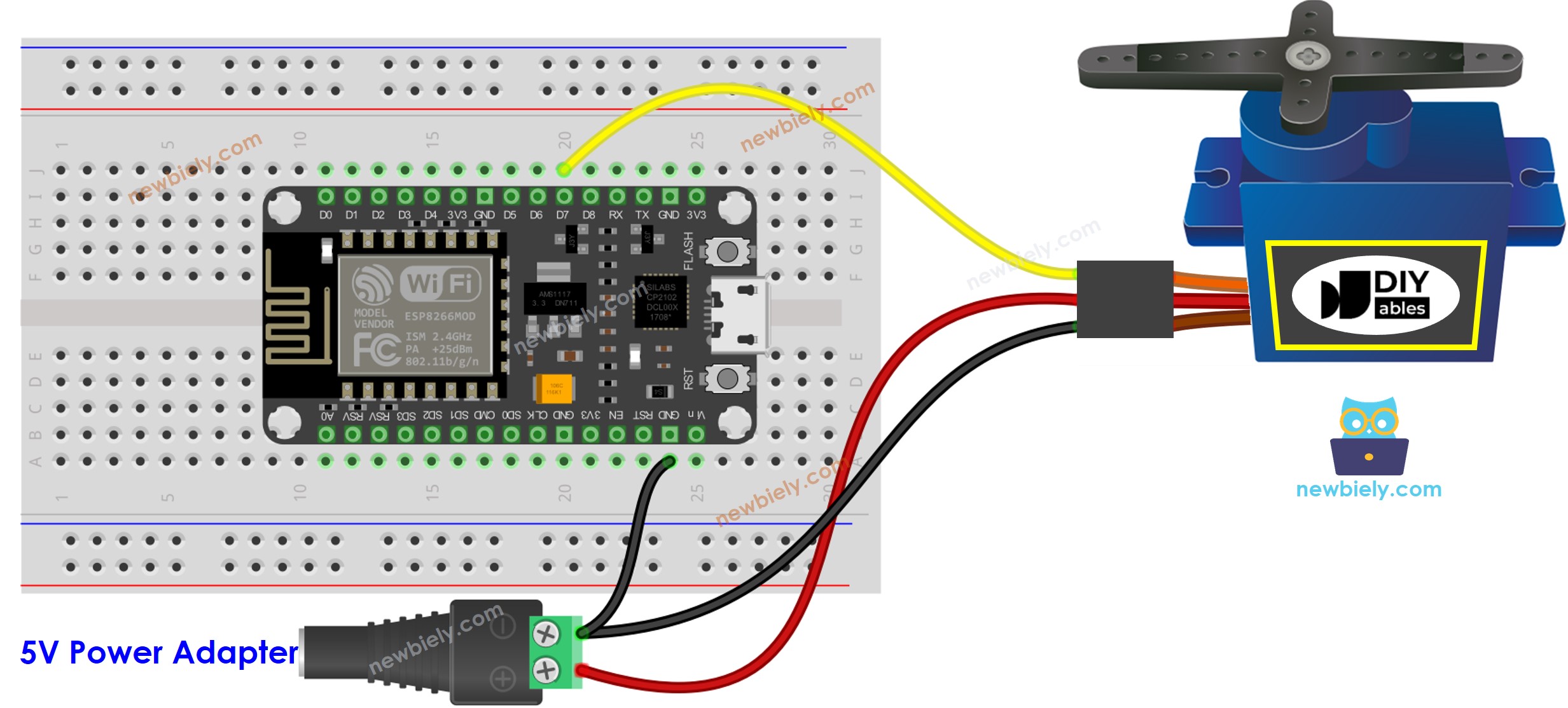
This image is created using Fritzing. Click to enlarge image
See more in ESP8266's pinout and how to supply power to the ESP8266 and other components.
How To Program For Servo Motor
The Arduino-ESP8266 core already comes with its built-in servo library, so we do not need to install it.
- Include the library:
- Create a Servo object:
If you have more than one servo motor, simply declare additional Servo objects:
- Assign the control pin of ESP8266 to the signal pin of the servo motor. For instance, pin D7:
- Finally, turn the servo motor to the required angle. For instance, 90°
ESP8266 Code
Detailed Instructions
To get started with ESP8266 on Arduino IDE, follow these steps:
- Check out the how to setup environment for ESP8266 on Arduino IDE tutorial if this is your first time using ESP8266.
- Wire the components as shown in the diagram.
- Connect the ESP8266 board to your computer using a USB cable.
- Open Arduino IDE on your computer.
- Choose the correct ESP8266 board, such as (e.g. NodeMCU 1.0 (ESP-12E Module)), and its respective COM port.
- Connect your ESP8266 to the PC using a USB cable.
- Launch the Arduino IDE, select the correct board and port.
- Copy the code provided and open it in the Arduino IDE.
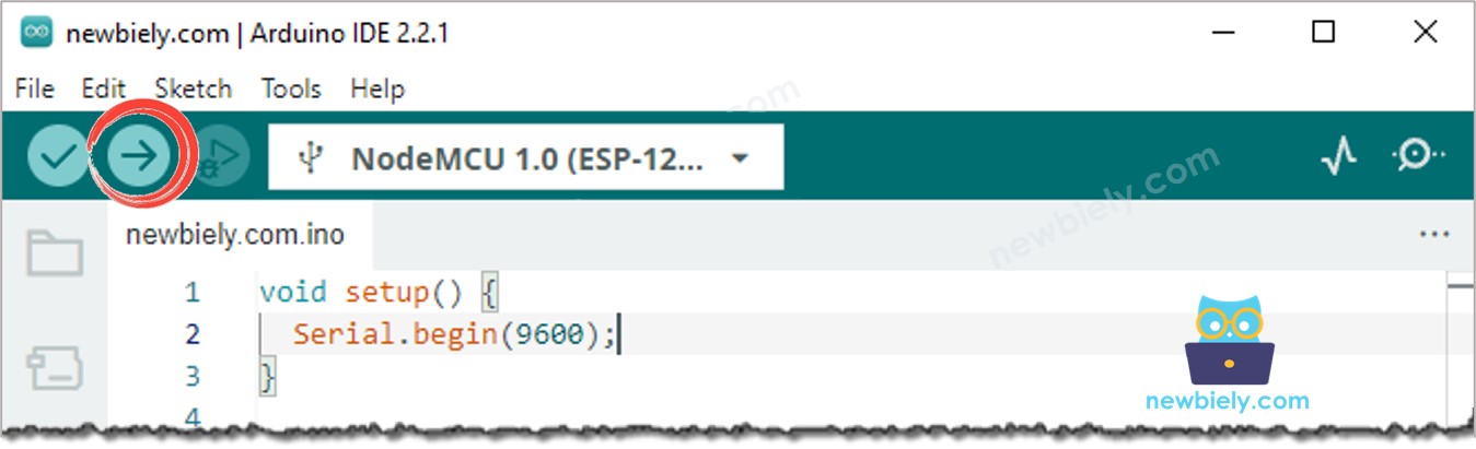
- Click the Upload button in the Arduino IDE to compile and upload the code to the ESP8266.
- Check out the outcome: The servo motor moves in a clockwise and counter-clockwise direction.
Code Explanation
Check out the line-by-line explanation contained in the comments of the source code!
How to Control Speed of Servo Motor
Utilizing the map() and millis() functions, we can regulate the speed of the servo motor in a smooth manner without hindering other code.