ESP8266 - IR Remote Control
You've probably come across the infrared remote control, also called the IR remote control, when using devices like TVs and air conditioners at home... This tutorial instructs you how to use the infrared (IR) remote control and an infrared receiver to control the ESP8266. In detail, we will learn:
- How to connect an IR receiver to ESP8266 board
- How to program ESP8266 to read the command from IR remote controller via IR receiver
Hardware Preparation
Or you can buy the following kits:
| 1 | × | DIYables Sensor Kit (18 sensors/displays) |
Additionally, some of these links are for products from our own brand, DIYables .
Overview of IR Remote Control
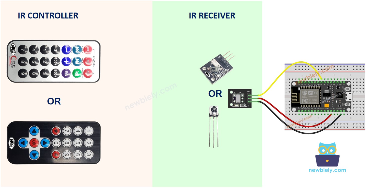
An IR control system has two components: an IR remote controller and an IR receiver.
- The IR remote controller is used to send commands using infrared signals.
- The IR receiver captures and interprets these signals to control the device.
An IR kit typically consists of the two components mentioned above: an IR remote controller and an IR receiver.
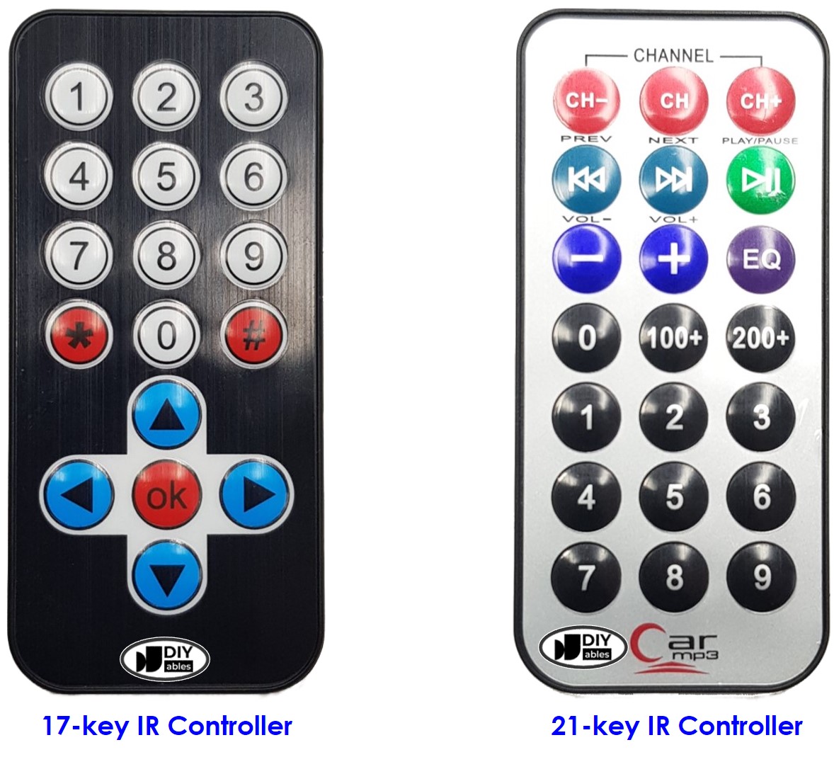
IR remote controller
The IR remote controller is a portable device that transmits infrared signals. It is equipped with a keypad featuring multiple buttons:
- Each button on the remote controller serves a distinct function or command.
- When a button is pressed, the remote controller emits an invisible infrared signal. This signal contains a special code or pattern linked to the pressed button.
- Since these infrared signals belong to the infrared spectrum, they cannot be seen by the human eye.
IR Receiver
The IR receiver module is a sensor that detects and receives the infrared signals emitted by the remote controller.
The infrared receiver detects the incoming infrared signals and converts them into the code (command) representing the button pressed on the remote controller.
The IR Receiver can be a sensor or a module. You can use the following choices:
- IR Receiver Module only
- IR Receiver Sensor only
- IR Receiver Sensor + Adapter
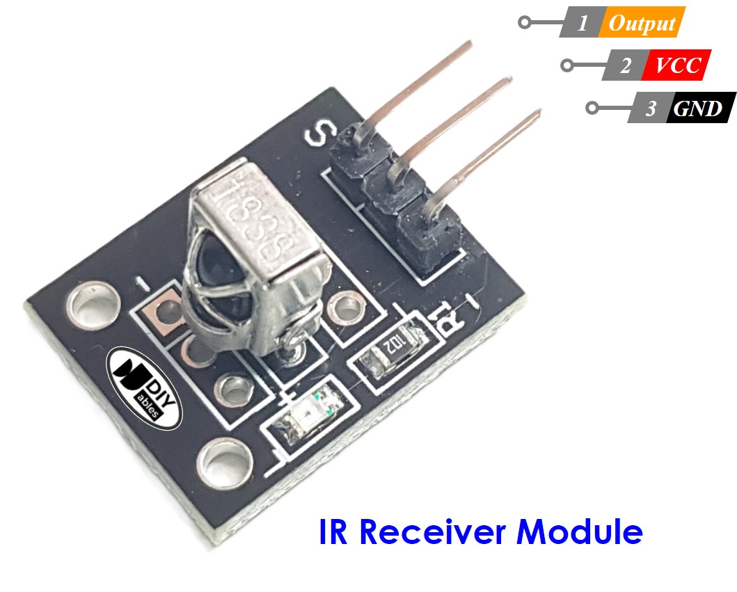
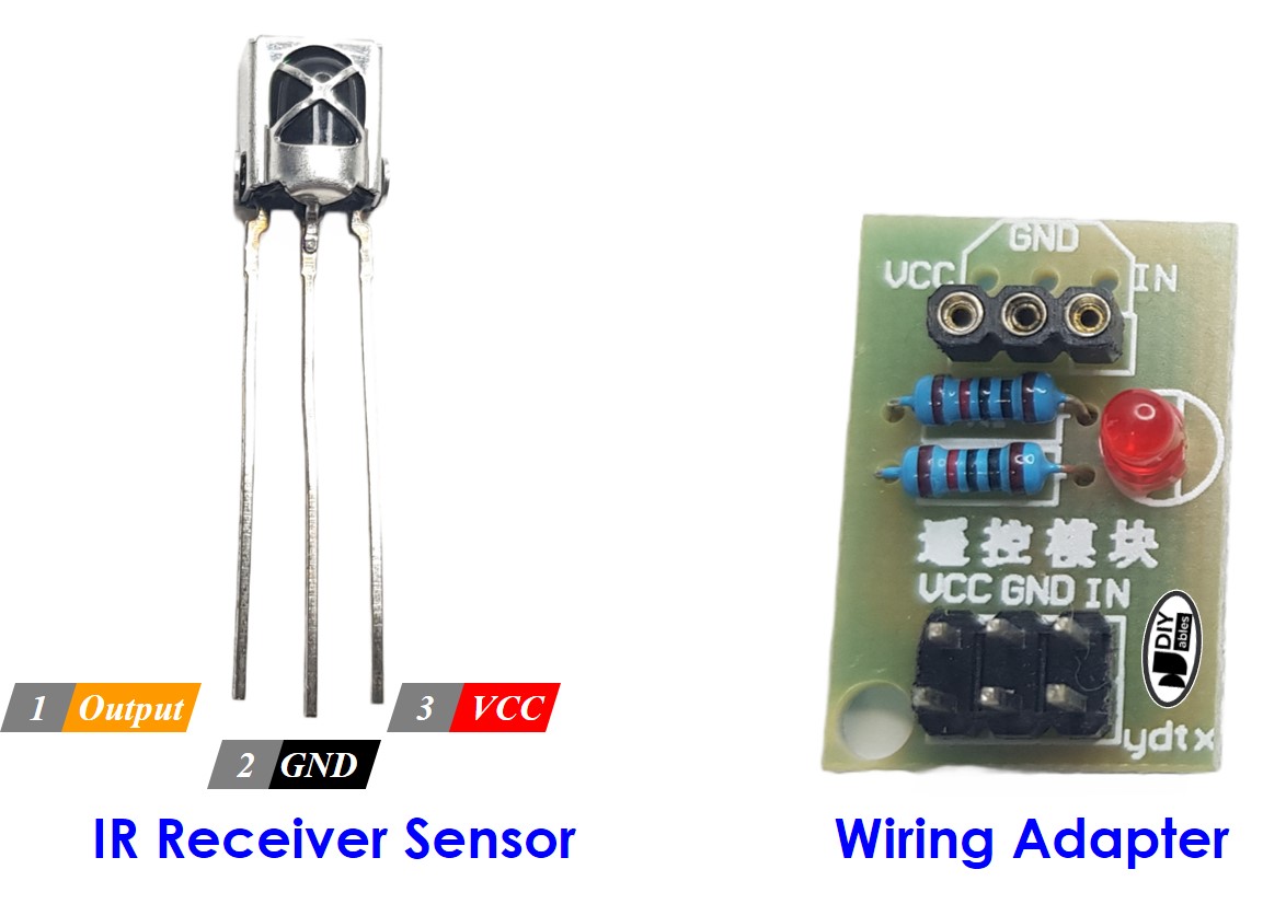
IR Receiver Pinout
IR receiver module or sensor has three pins:
- VCC pin: Connect this pin to the 3.3V or 5V pin of the ESP8266 or external power source.
- GND pin: Connect this pin to GND pin of the ESP8266 or external power source..
- OUT (Output) pin: This pin is the output pin of the IR receiver module. Connected to a digital input pin on the ESP8266.
How It Works
When a user presses a button on the IR remote controller, the following actions take place:
- The IR remote controller converts the button's command into an infrared signal using a specific protocol.
- The IR remote controller emits the encoded infrared signal.
- The IR receiver picks up the emitted infrared signal.
- The IR receiver decodes the infrared signal, translating it back into the original command.
- The ESP8266 reads and receives the command from the IR receiver.
- The ESP8266 maps the received command to the corresponding button pressed on the IR remote controller.
In summary, these steps illustrate how the IR remote controller's button press is converted into an understandable command that can be utilized by the ESP8266.
Don't worry if it seems complicated. With the assistance of the DIYables_IRcontroller library, it becomes incredibly easy.
Wiring Diagram
Wiring diagram between ESP8266 and IR Receiver Module
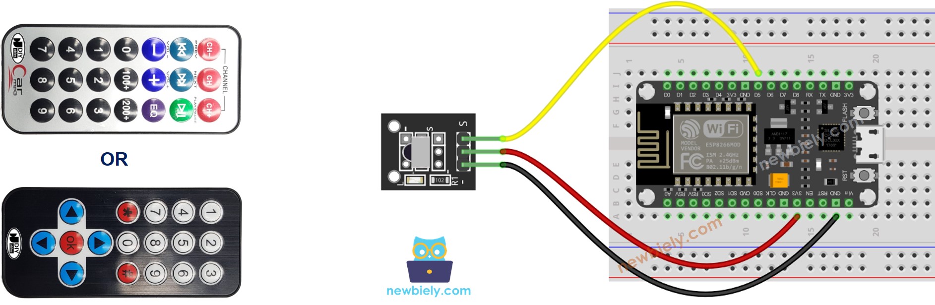
This image is created using Fritzing. Click to enlarge image
Wiring diagram between ESP8266 and IR Receiver Sensor
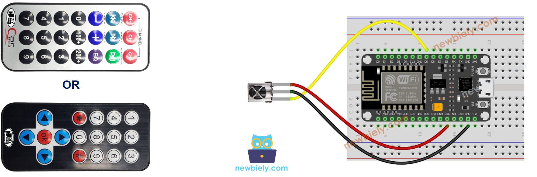
This image is created using Fritzing. Click to enlarge image
See more in ESP8266's pinout and how to supply power to the ESP8266 and other components.
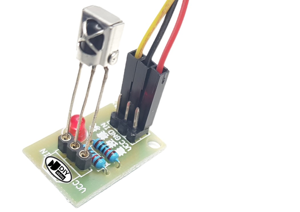
Wiring diagram between ESP8266 and IR Receiver Sensor and Adapter
Before connecting the IR receiver sensor to the ESP8266, you have the option to connect it to the adapter. This allows for easier setup and ensures proper connection between the IR receiver sensor and the ESP8266.
How To Program For IR Remote Controller
- Include the library:
- Declare a DIYables_IRcontroller_17 or DIYables_IRcontroller_21 object corresponds with 17-key or 21-key IR remote controllers:
- Initialize the IR Controller.
- In the loop, check if a key is pressed or not. If yes, get the key
- After detecting a key press, you can perform specific actions based on each key.
ESP8266 Code
- ESP8266 code for DIYables 17-key IR remote controller
- ESP8266 code for DIYables 21-key IR remote controller
Detailed Instructions
To get started with ESP8266 on Arduino IDE, follow these steps:
- Check out the how to setup environment for ESP8266 on Arduino IDE tutorial if this is your first time using ESP8266.
- Wire the components as shown in the diagram.
- Connect the ESP8266 board to your computer using a USB cable.
- Open Arduino IDE on your computer.
- Choose the correct ESP8266 board, such as (e.g. NodeMCU 1.0 (ESP-12E Module)), and its respective COM port.
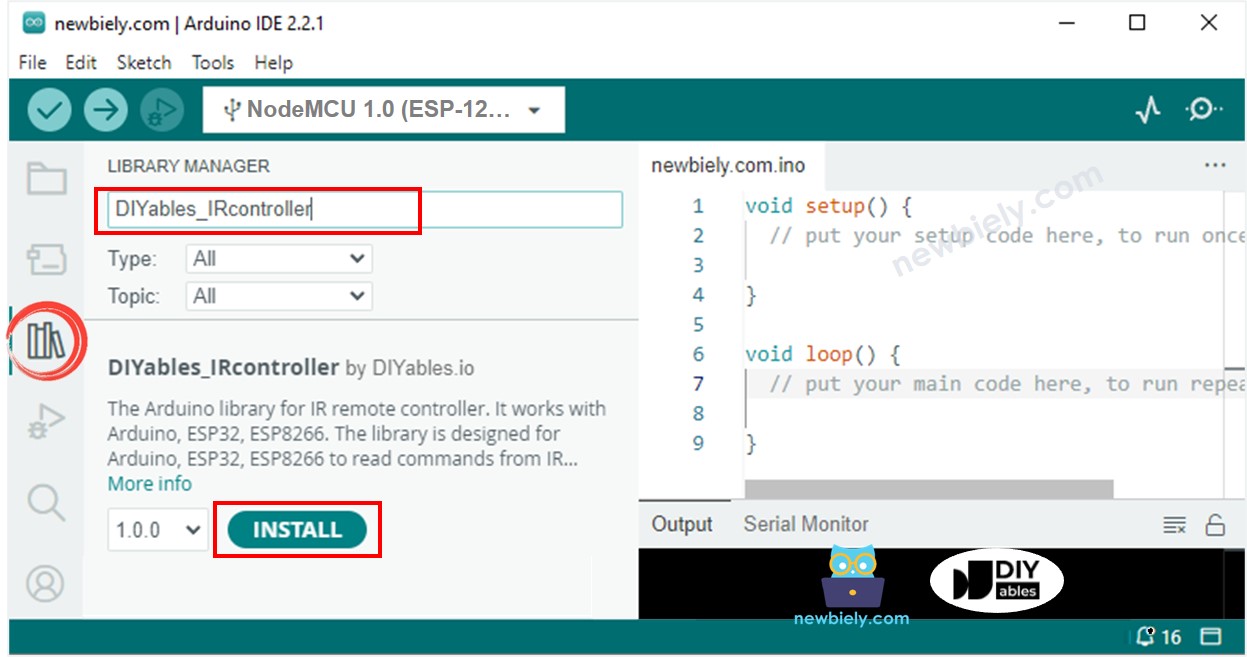
- Click to the Libraries icon on the left bar of the Arduino IDE.
- Search "DIYables_IRcontroller", then find the DIYables_IRcontroller library by DIYables
- Click Install button to install DIYables_IRcontroller library.
- You will be asked for installing the library dependency as below image:
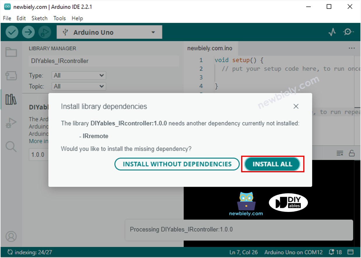
- Click Install all button to install the dependency
- Copy the above code and open with Arduino IDE
- Click Upload button on Arduino IDE to upload code to ESP8266
- Press keys on the remote controller one by one
- Check out the result on the Serial Monitor.
- When you press the keys on a 17-key IR controller one by one, the following is the result:
You now have the ability to customize the code and control different devices like LEDs, fans, pumps, actuators, and more using IR remote controllers. This means you can make changes to the code to make these devices respond to your commands sent through the remote control.