Disclosure: Some of the links provided in this section are Amazon affiliate links. We may receive a commission for any purchases made through these links at no additional cost to you. Additionally, some of these links are for products from our own brand, DIYables .
If you are unfamiliar with the RFID/NFC RC522 Module and Servo Motor (including pinout, functioning, and programming), check out the following tutorials:
Some UIDs of RFID/NFC tags are already programmed into the ESP8266 code.
When a user taps an RFID/NFC tag onto the RFID/NFC reader, the reader reads the UID from the tag.
The ESP8266 then receives the UID from the reader.
It compares the read UID with the predefined UIDs that were set in the code.
If the UID matches one of the predefined UIDs, the ESP8266 will control the servo motor to 90°.
When the tag is tapped again, the ESP8266 will control the servo motor back to 0°.
This process will repeat indefinitely.
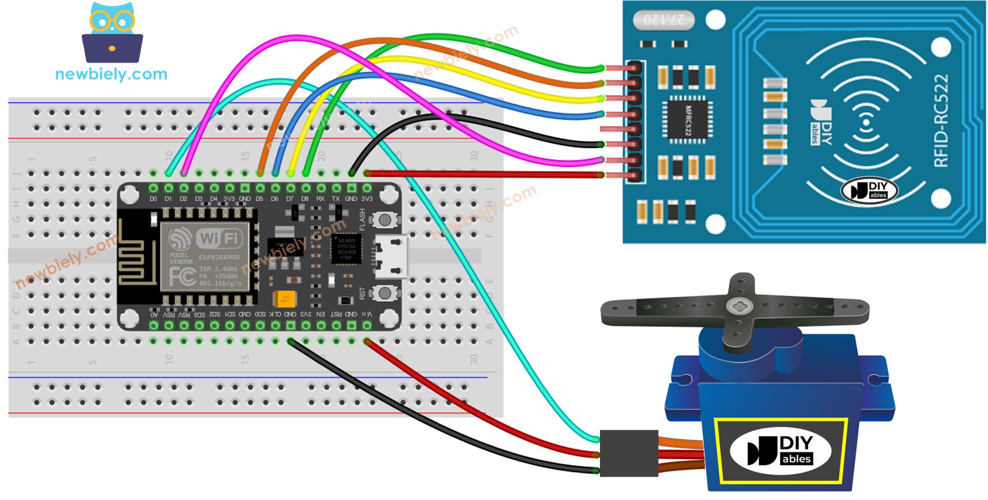
Wiring Diagram
This image is created using Fritzing. Click to enlarge image
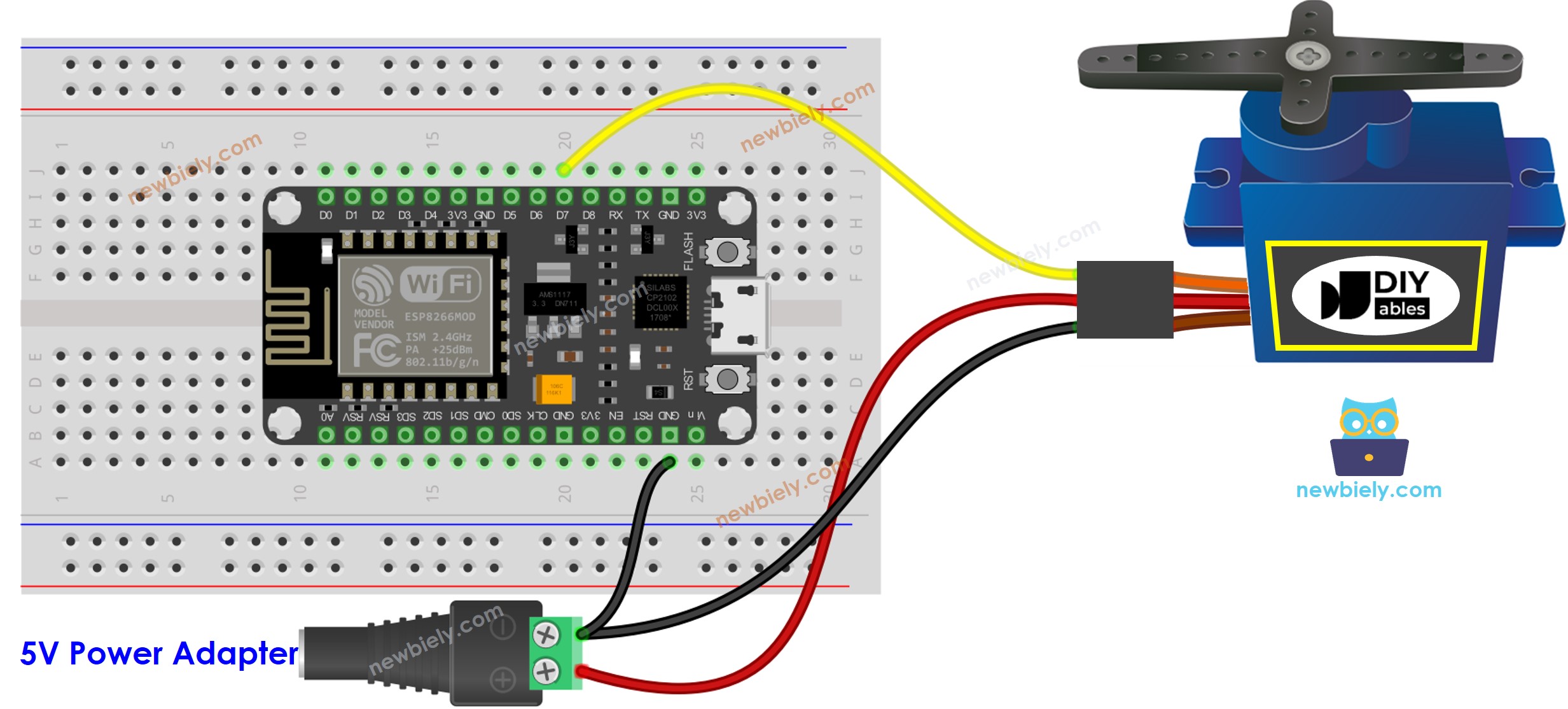
For the sake of simplicity, the above wiring diagram is utilized for testing or learning purposes, and for a small-torque servo motor. In actuality, we strongly suggest using an external power supply for the servo motor. The wiring diagram below illustrates how to connect the servo motor to an external power source.
This image is created using Fritzing. Click to enlarge image
The arrangement of pins may differ depending on the manufacturer. ALWAYS use the labels printed on the module. The image above displays the pinout of modules from DIYables producer.
Wiring table of RFID/NFC RC522 Module
RFID/NFC RC522
ESP8266
SS
→ GPIO 5 (SPI CS/SS)
SCK
→ GPIO 8 (SPI CLK)
MOSI
→ GPIO 7 (SPI MOSI)
MISO
→ GPIO 6 (SPI MISO)
IRQ(not connected)
GND
→ GND
RST
→ TO_BE_UPDATED
VCC
→ 3.3V
ESP8266 Code - Single RFID/NFC Tag
/* * This ESP8266 NodeMCU code was developed by newbiely.com * * This ESP8266 NodeMCU code is made available for public use without any restriction * * For comprehensive instructions and wiring diagrams, please visit: * https://newbiely.com/tutorials/esp8266/esp8266-rfid-servo-motor */#include <SPI.h>#include <MFRC522.h>#include <Servo.h>#define SS_PIN D8 // The ESP8266 pin D8#define RST_PIN D2 // The ESP8266 pin D2#define SERVO_PIN D1 // The ESP8266 pin connects to servo motorMFRC522 rfid(SS_PIN, RST_PIN);Servo servo;byte authorizedUID[4] = {0xFF, 0xFF, 0xFF, 0xFF};int angle = 0; // The current angle of servo motorvoidsetup() {Serial.begin(9600);SPI.begin(); // init SPI bus rfid.PCD_Init(); // init MFRC522 servo.attach(SERVO_PIN); servo.write(angle); // rotate servo motor to 0°Serial.println("Tap RFID/NFC Tag on reader");}voidloop() {if (rfid.PICC_IsNewCardPresent()) { // new tag is availableif (rfid.PICC_ReadCardSerial()) { // NUID has been readedMFRC522::PICC_Type piccType = rfid.PICC_GetType(rfid.uid.sak);if (rfid.uid.uidByte[0] == authorizedUID[0] && rfid.uid.uidByte[1] == authorizedUID[1] && rfid.uid.uidByte[2] == authorizedUID[2] && rfid.uid.uidByte[3] == authorizedUID[3] ) {Serial.println("Authorized Tag");// change angle of servo motorif (angle == 0) angle = 90;else//if(angle == 90) angle = 0;// rotate the servo motor to the angle position servo.write(angle);Serial.print("Rotate Servo Motor to ");Serial.print(angle);Serial.println("°"); } else {Serial.print("Unauthorized Tag with UID:");for (int i = 0; i < rfid.uid.size; i++) {Serial.print(rfid.uid.uidByte[i] < 0x10 ? " 0" : " ");Serial.print(rfid.uid.uidByte[i], HEX); }Serial.println(); } rfid.PICC_HaltA(); // halt PICC rfid.PCD_StopCrypto1(); // stop encryption on PCD } }}
Detailed Instructions
To get started with ESP8266 on Arduino IDE, follow these steps:
Connect the ESP8266 board to your computer using a USB cable.
Open Arduino IDE on your computer.
Choose the correct ESP8266 board, such as (e.g. NodeMCU 1.0 (ESP-12E Module)), and its respective COM port.
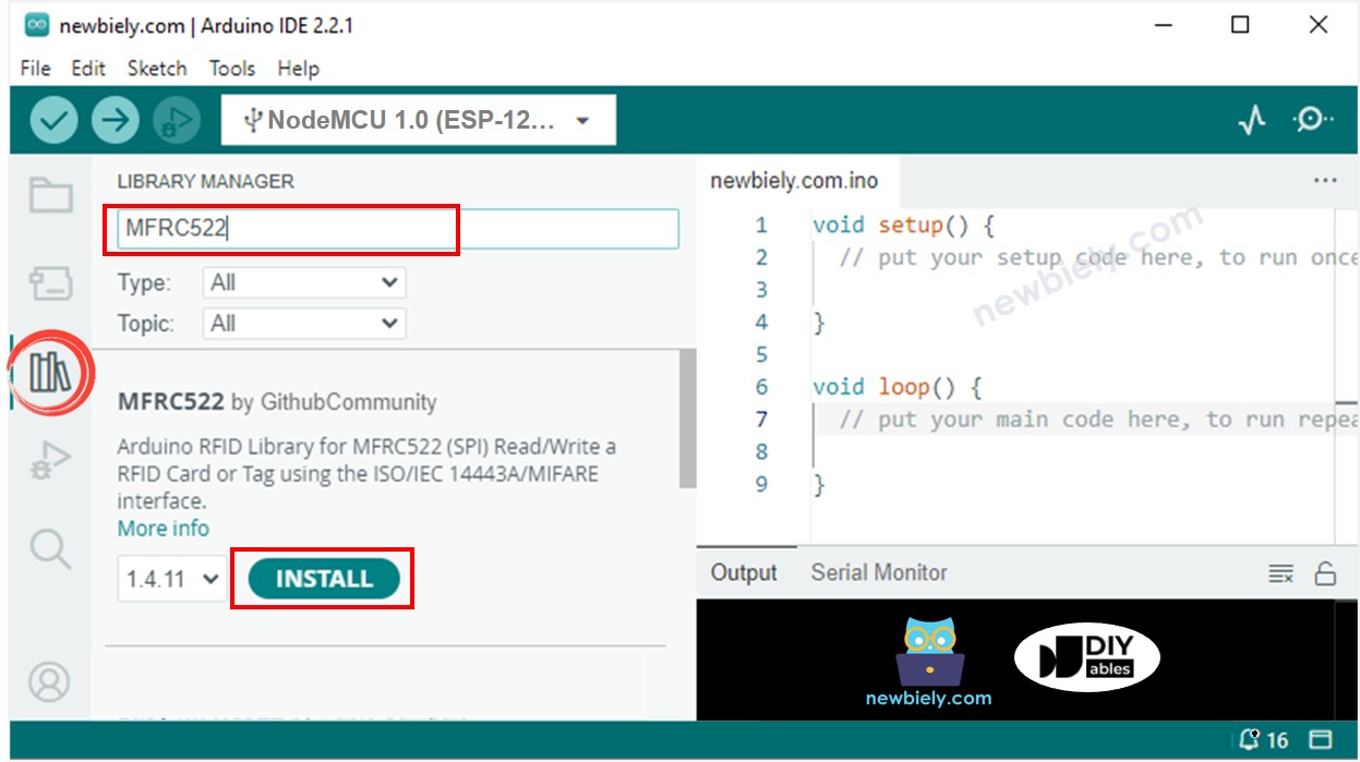
Click to the Libraries icon on the left bar of the Arduino IDE.
Search for “MFRC522” and locate the library by GithubCommunity.
Press the Install button to install the MFRC522 library.
In order to discover the UID of an RFID/NFC tag, the first step is to upload code to ESP8266 using the Arduino IDE and then click the Upload button. After that, open the Serial Monitor and tap the tag onto the RFID-RC522 module. The UID will be displayed on the Serial Monitor.
Newbiely | Arduino IDE 2.3.8
──
☐
✕
File
Edit
Sketch
Tools
Help
Nodemcu 1.0 (ESP-12E Module)
Newbiely.ino
···
8Serial.println("Hello World!");
Output
Serial Monitor
Message (Enter to send message to 'Nodemcu 1.0 (ESP-12E Module)' on 'COM15')
New Line
9600 baud
Tap RFID/NFC tag on reader
Unauthorized Tag with UID: 3A C9 6A CB
Ln 11, Col 1
Nodemcu 1.0 (ESP-12E Module) on COM15
2
Once you have your UID:
Replace the UID in line 20 of the code with your own. For example, change byte authorizedUID[4] = {0xFF, 0xFF, 0xFF, 0xFF}; to byte authorizedUID[4] = {0x3A, 0xC9, 0x6A, 0xCB};
Upload the code to your ESP8266 board
Tap an RFID/NFC tag on the RFID-RC522 module
The servo motor should rotate to 90°
Check the output on the Serial Monitor
Newbiely | Arduino IDE 2.3.8
──
☐
✕
File
Edit
Sketch
Tools
Help
Nodemcu 1.0 (ESP-12E Module)
Newbiely.ino
···
8Serial.println("Hello World!");
Output
Serial Monitor
Message (Enter to send message to 'Nodemcu 1.0 (ESP-12E Module)' on 'COM15')
New Line
9600 baud
Tap RFID/NFC tag on reader
Authorized Tag
Rotate Servo Motor to 90°
Ln 11, Col 1
Nodemcu 1.0 (ESP-12E Module) on COM15
2
Tap the RFID/NFC tag on the RFID-RC522 module once more.
The servo motor will rotate to 0°, and you can observe this on the Serial Monitor.
Newbiely | Arduino IDE 2.3.8
──
☐
✕
File
Edit
Sketch
Tools
Help
Nodemcu 1.0 (ESP-12E Module)
Newbiely.ino
···
8Serial.println("Hello World!");
Output
Serial Monitor
Message (Enter to send message to 'Nodemcu 1.0 (ESP-12E Module)' on 'COM15')
New Line
9600 baud
Tap RFID/NFC tag on reader
Authorized Tag
Rotate Servo Motor to 90°
Authorized Tag
Rotate Servo Motor to 0°
Ln 11, Col 1
Nodemcu 1.0 (ESP-12E Module) on COM15
2
Tap an RFID/NFC tag to the RFID-RC522 module.
Check the Serial Monitor for the output.
Newbiely | Arduino IDE 2.3.8
──
☐
✕
File
Edit
Sketch
Tools
Help
Nodemcu 1.0 (ESP-12E Module)
Newbiely.ino
···
8Serial.println("Hello World!");
Output
Serial Monitor
Message (Enter to send message to 'Nodemcu 1.0 (ESP-12E Module)' on 'COM15')
New Line
9600 baud
Tap RFID/NFC tag on reader
Authorized Tag
Rotate Servo Motor to 90°
Authorized Tag
Rotate Servo Motor to 0°
Unauthorized Tag with UID: BD 1E 1D 00
Ln 11, Col 1
Nodemcu 1.0 (ESP-12E Module) on COM15
2
ESP8266 Code - Multiple RFID/NFC Tags
We can enable multiple RFID/NFC tags to control a servo motor. As an example, the code below uses two tags.
/* * This ESP8266 NodeMCU code was developed by newbiely.com * * This ESP8266 NodeMCU code is made available for public use without any restriction * * For comprehensive instructions and wiring diagrams, please visit: * https://newbiely.com/tutorials/esp8266/esp8266-rfid-servo-motor */#include <SPI.h>#include <MFRC522.h>#include <Servo.h>#define SS_PIN D8 // The ESP8266 pin D8#define RST_PIN D2 // The ESP8266 pin D2#define SERVO_PIN D1 // The ESP8266 pin connects to servo motorMFRC522 rfid(SS_PIN, RST_PIN);Servo servo;byte authorizedUID1[4] = {0x3A, 0xC9, 0x6A, 0xCB};byte authorizedUID2[4] = {0x30, 0x01, 0x8B, 0x15};int angle = 0; // The current angle of servo motorvoidsetup() {Serial.begin(9600);SPI.begin(); // init SPI bus rfid.PCD_Init(); // init MFRC522 servo.attach(SERVO_PIN); servo.write(angle); // rotate servo motor to 0°Serial.println("Tap RFID/NFC Tag on reader");}voidloop() {if (rfid.PICC_IsNewCardPresent()) { // new tag is availableif (rfid.PICC_ReadCardSerial()) { // NUID has been readedMFRC522::PICC_Type piccType = rfid.PICC_GetType(rfid.uid.sak);if (rfid.uid.uidByte[0] == authorizedUID1[0] && rfid.uid.uidByte[1] == authorizedUID1[1] && rfid.uid.uidByte[2] == authorizedUID1[2] && rfid.uid.uidByte[3] == authorizedUID1[3] ) {Serial.println("Authorized Tag 1"); changeServo(); } elseif (rfid.uid.uidByte[0] == authorizedUID2[0] && rfid.uid.uidByte[1] == authorizedUID2[1] && rfid.uid.uidByte[2] == authorizedUID2[2] && rfid.uid.uidByte[3] == authorizedUID2[3] ) {Serial.println("Authorized Tag 2"); changeServo(); } else {Serial.print("Unauthorized Tag with UID:");for (int i = 0; i < rfid.uid.size; i++) {Serial.print(rfid.uid.uidByte[i] < 0x10 ? " 0" : " ");Serial.print(rfid.uid.uidByte[i], HEX); }Serial.println(); } rfid.PICC_HaltA(); // halt PICC rfid.PCD_StopCrypto1(); // stop encryption on PCD } }}void changeServo() {// change angle of servo motorif (angle == 0) angle = 90;else//if(angle == 90) angle = 0;// rotate the servo motor to the angle position servo.write(angle);Serial.print("Rotate Servo Motor to ");Serial.print(angle);Serial.println("°");}
Repeat the same steps as before, and then tap each tag to the RFID-RC522 module. The output on the Serial Monitor should appear like this:
Newbiely | Arduino IDE 2.3.8
──
☐
✕
File
Edit
Sketch
Tools
Help
Nodemcu 1.0 (ESP-12E Module)
Newbiely.ino
···
8Serial.println("Hello World!");
Output
Serial Monitor
Message (Enter to send message to 'Nodemcu 1.0 (ESP-12E Module)' on 'COM15')
New Line
9600 baud
Tap RFID/NFC tag on reader
Authorized Tag 2
Rotate Servo Motor to 90°
Authorized Tag 1
Rotate Servo Motor to 0°
Ln 11, Col 1
Nodemcu 1.0 (ESP-12E Module) on COM15
2
You can expand the code written above to include three, four, or more tags.
Please feel free to share the link of this tutorial. However, Please do not use our content on any other websites. We invested a lot of effort and time to create the content, please respect our work!