ESP8266 - Keypad - Relay
This tutorial instructs you how to use an ESP8266 and a keypad to control a relay. When the user enters the correct password on the keypad, the ESP8266 will activate the relay.
The tutorial additionally provides the ESP8266 code that activates a relay for a certain duration and then deactivates it without utilizing the delay() function. The ESP8266 code also accepts multiple passwords.
By attaching a relay to an Electromagnetic Lock, a Solenoid Lock, a Linear Actuator, a Heating Element, a Pump, or a Fan ... We can then use a keypad to control them.
Hardware Preparation
Or you can buy the following kits:
| 1 | × | DIYables Sensor Kit (18 sensors/displays) |
Additionally, some of these links are for products from our own brand, DIYables .
Overview of Keypad and Relay
If you are unfamiliar with keypad and relay (including pinout, operation, programming, etc.), the following tutorials can help:
- ESP8266 - Keypad tutorial
- ESP8266 - Relay tutorial
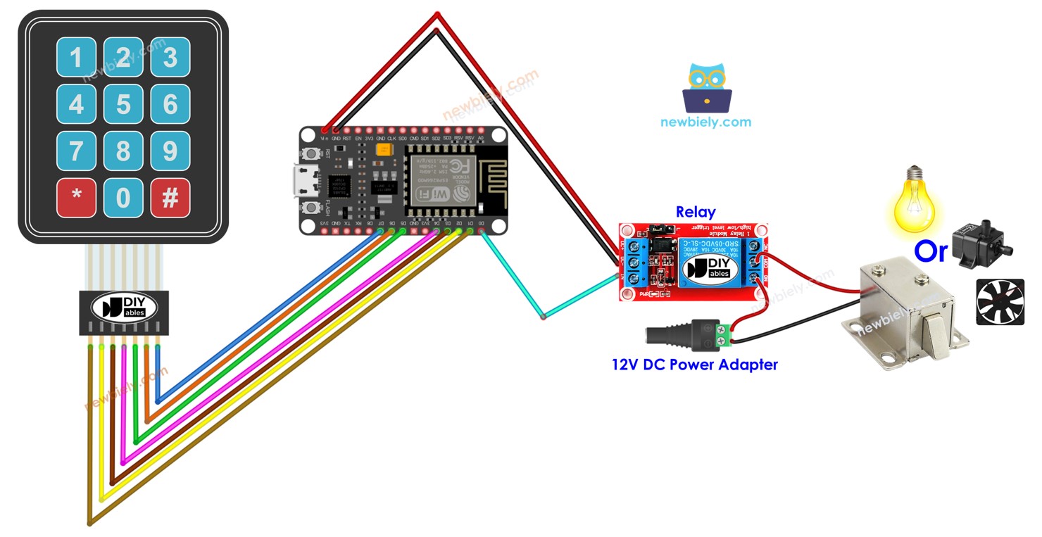
Wiring Diagram
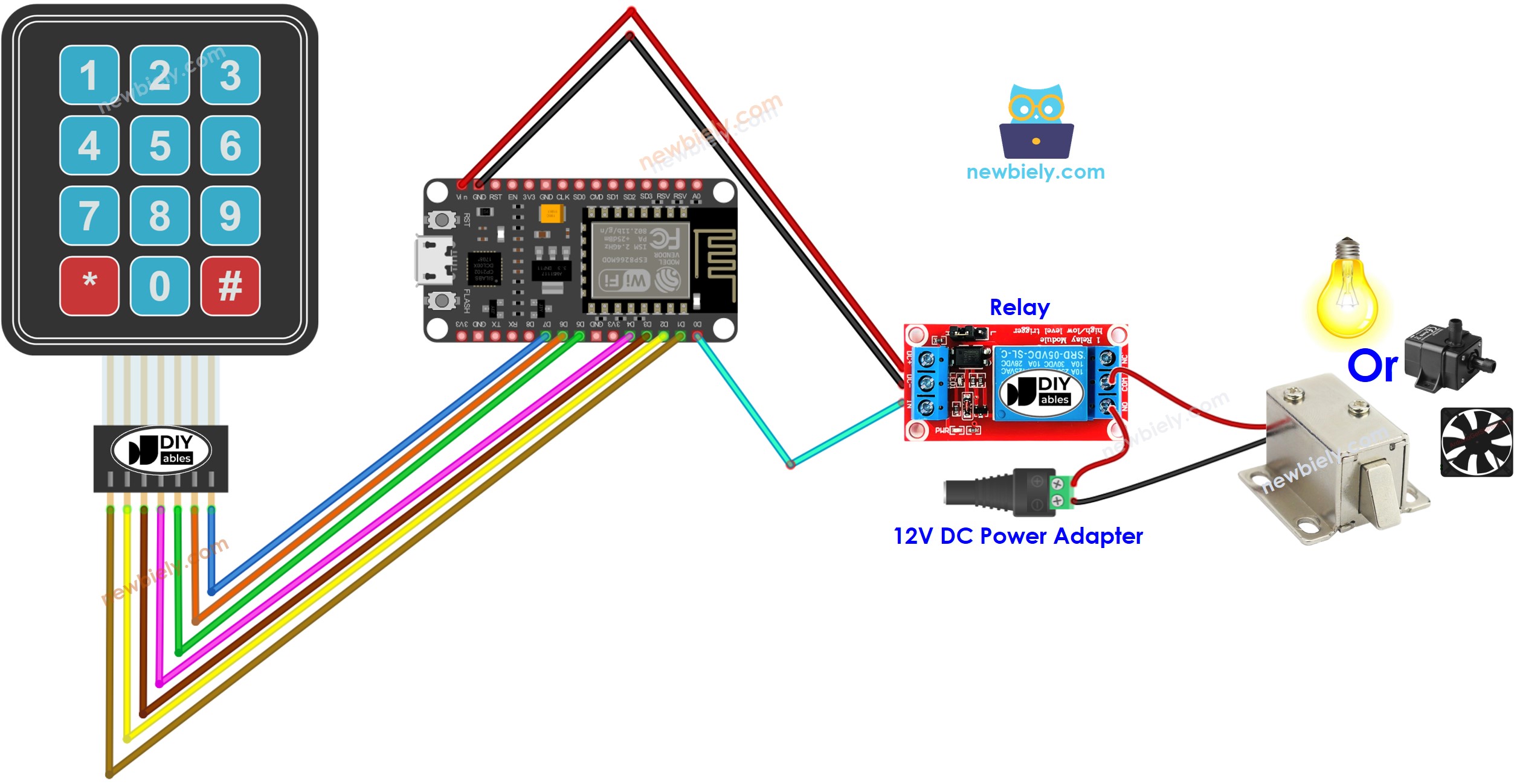
This image is created using Fritzing. Click to enlarge image
See more in ESP8266's pinout and how to supply power to the ESP8266 and other components.
ESP8266 Code - turn relay on if the password is correct
If the password is correct, the following code will activate a relay.
Detailed Instructions
To get started with ESP8266 on Arduino IDE, follow these steps:
- Check out the how to setup environment for ESP8266 on Arduino IDE tutorial if this is your first time using ESP8266.
- Wire the components as shown in the diagram.
- Connect the ESP8266 board to your computer using a USB cable.
- Open Arduino IDE on your computer.
- Choose the correct ESP8266 board, such as (e.g. NodeMCU 1.0 (ESP-12E Module)), and its respective COM port.
- Connect a USB cable to the ESP8266 and the PC.
- Open the Arduino IDE, select the appropriate board and port.
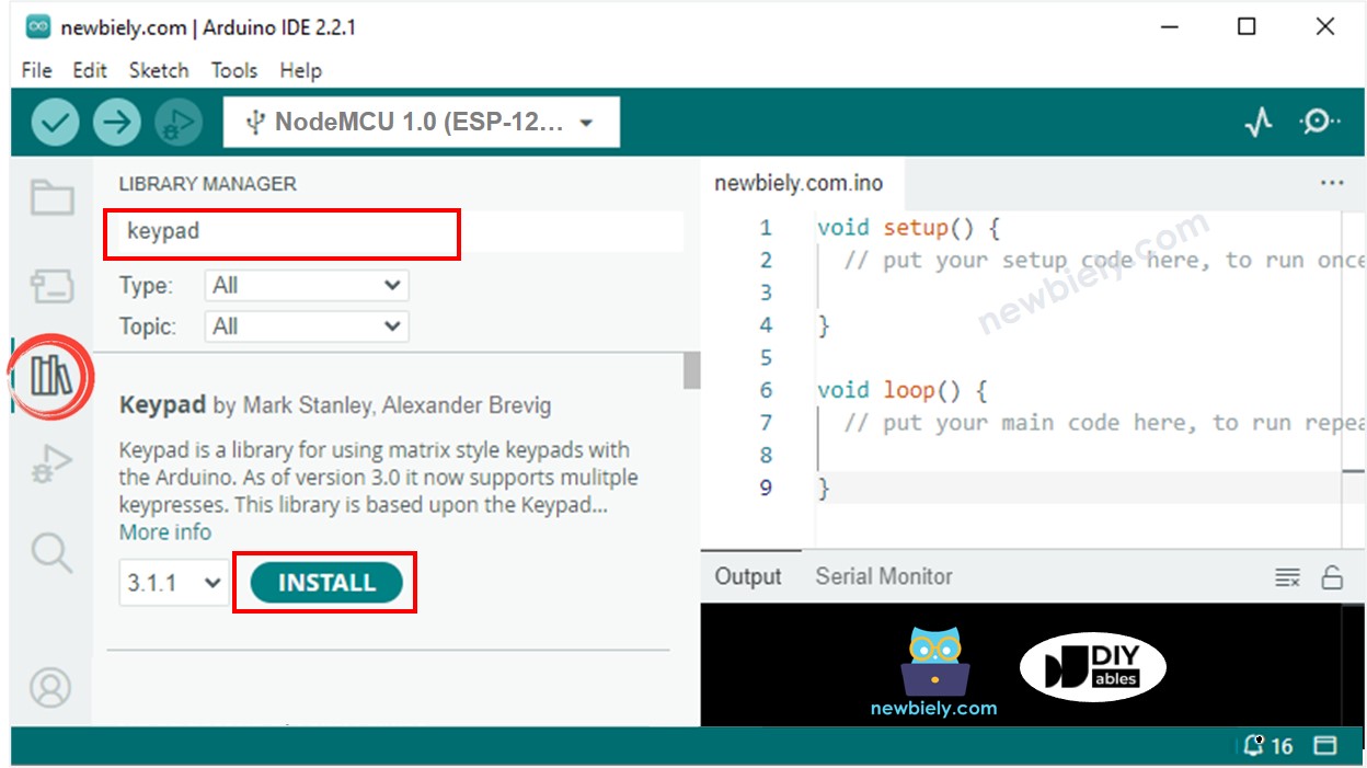
- Click to the Libraries icon on the left bar of the Arduino IDE.
- Search for “keypad” and locate the keypad library created by Mark Stanley and Alexander Brevig.
- Then, press the Install button to add the keypad library.
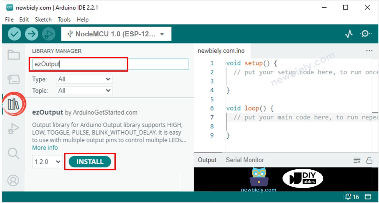
- Look for “ezOutput” and locate the ezOutput library from ArduinoGetStarted.
- Press the Install button to install the ezOutput library.
- Copy the code and open it in the Arduino IDE.
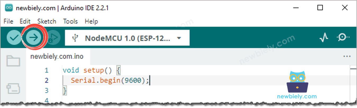
- Click the Upload button in the Arduino IDE to send the code to the ESP8266.
- Tap in 1234 and then press #.
- Afterwards, enter 9765 and hit #.
- Check the Serial Monitor for the output and the state of the relay.
Code Explanation
Authorized passwords are pre-defined in the ESP8266 code. A string is used to store the password inputted by users, referred to as input string. On the keypad, two keys (* and #) are used for special purposes: to clear the password and to terminate the password. When a key on the keypad is pressed:
- If the pressed key is not either of the two special keys, it is added to the input string.
- If the pressed key is *, the input string is cleared. This can be utilized to start or restart entering the password.
- If the pressed key is #:
- The ESP8266 checks if input string match with one of the pre-defined passwords, the relay is turned on.
- Regardless of whether the password is correct or not, the input string is cleared for the next input.
ESP8266 Code - turn a relay on in a period of time if the password is correct
If the password is correct, the relay is switched on for 5 seconds. After that, the relay is turned off.