ESP8266 - LED Strip
In this tutorial, we are going to learn how to program ESP8266 to control a LED strip to emit the light.
Hardware Preparation
Or you can buy the following kits:
| 1 | × | DIYables Sensor Kit (18 sensors/displays) |
Additionally, some of these links are for products from our own brand, DIYables .
Overview of LED Strip
A LED strip, also known as LED tape or LED ribbon, is a flexible circuit board with surface-mounted LEDs that emit light. These strips are versatile and commonly used for decorative lighting in various applications. LED strips come in a range of colors and are often used to provide ambient lighting, accent lighting, or decorative lighting effects.
LED strips come in two main types:
- Addressable LED Strips: In this type, the color and brightness of each individual LED on the strip can be independently controlled. This capability is due to the fact that each LED is assigned a specific address.
- Non-Addressable LED Strips: In contrast, non-addressable LED strips allow control over the color and brightness, but this control applies uniformly to all LEDs on the strip.
This tutorial will focus on the Non-Addressable LED Strips. For Addressable LED Strips, please refer to the following tutorials:
- ESP8266 - NeoPixel LED Strip tutorial
- ESP8266 - WS2812B LED Strip tutorial
- ESP8266 - DotStar LED Strip tutorial
Non-Addressable LED Strip Pinout
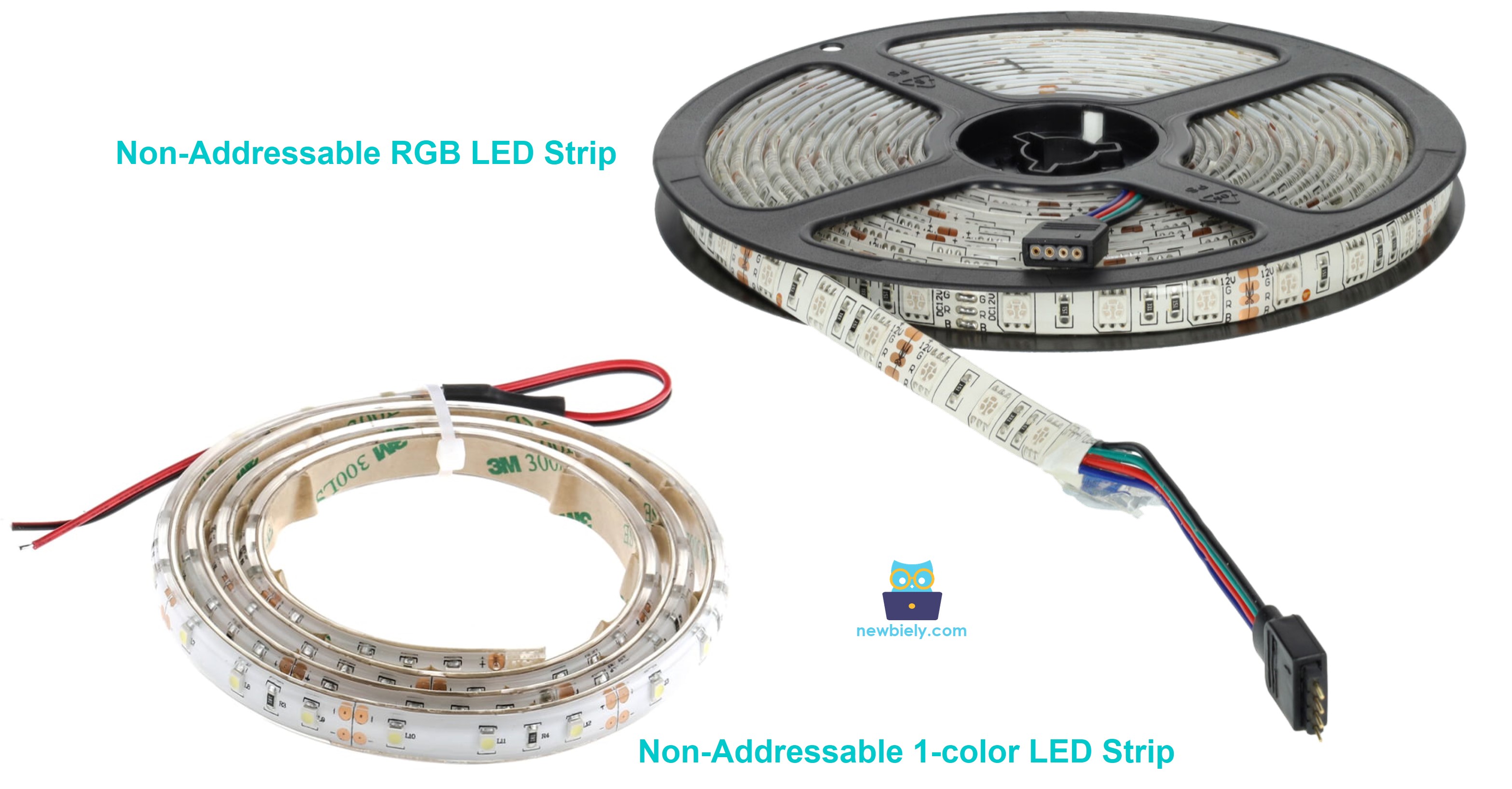
Non-Addressable LED Strip has two main types:
- Non-Addressable 1-color LED strip: Only one color defined by manufacturer.
- Non-Addressable RGB LED strip: any colors
A Non-Addressable 1-color LED Strip usually has two pins:
- 12V/24V pin: needs to be connected to the positive pin of 12V or 24V DC power supply
- GND pin: needs to be connected to the negative pin of 12V or 24V DC power supply
A Non-Addressable RGB LED Strip usually has four pins:
- 12V/24V pin: needs to be connected to the positive pin of 12V or 24V DC power supply
- R pin: This pin is used to control the red color. Connecting this pin to the negative pin of the power supply enables the red color
- G pin: This pin is used to control the green color. Connecting this pin to the negative pin of the power supply enables the green color
- B pin: This pin is used to control the blue color. Connecting this pin to the negative pin of the power supply enables the blue color
We will learn how to control the both types by ESP8266 one-by-one.
How to Control a Non-Addressable 1-color LED strip.
If 12V LED strip is powered by 12V power supply, it emits light. To control a 12V LED strip, we need to use a relay in between ESP8266 and 12V LED strip. ESP8266 can control the 12V LED strip via the relay. If you do not know about relay (pinout, how it works, how to program ...), learn about relay in the ESP8266 - Relay tutorial
Wiring Diagram.
Wiring Diagram between ESP8266 and Non-Addressable 1-color LED strip.
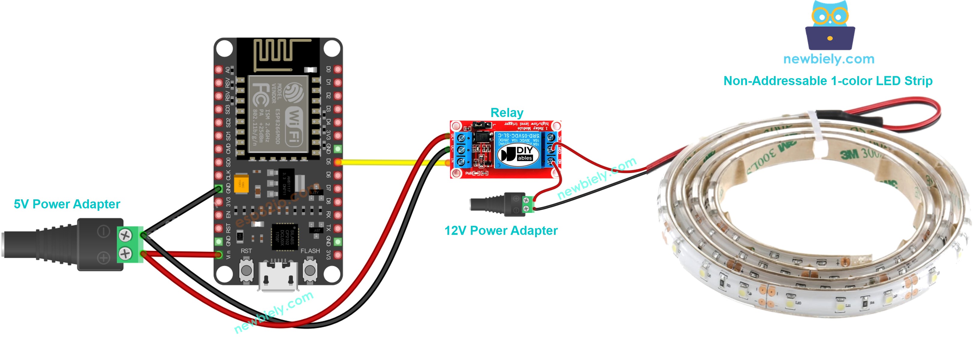
This image is created using Fritzing. Click to enlarge image
Wiring Diagram between ESP8266 and Non-Addressable RGB LED strip.
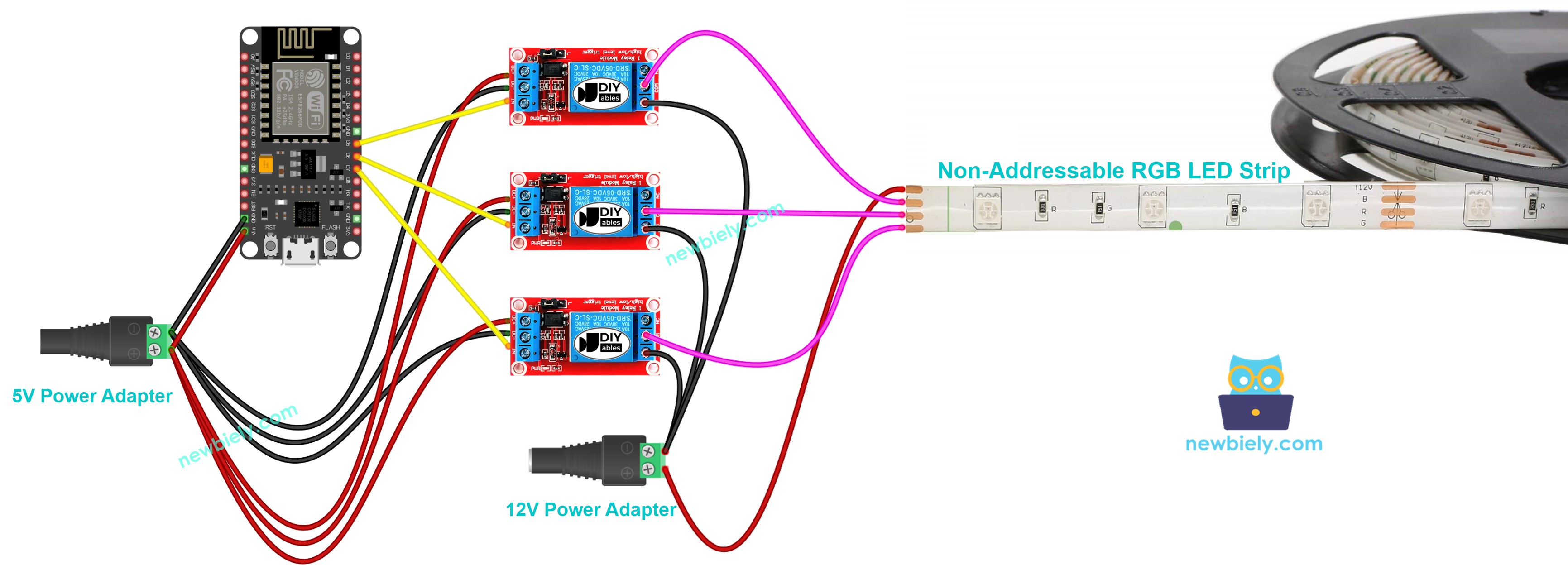
This image is created using Fritzing. Click to enlarge image
See more in ESP8266's pinout and how to supply power to the ESP8266 and other components.
ESP8266 Code
ESP8266 Code for controlling Non-Addressable 1-color LED strip.
The below code repeatedly turns the LED strip ON in 5 seconds and OFF in 5 seconds,
ESP8266 Code for controlling Non-Addressable RGB LED strip.
The below code repeatedly control the color of the RGB LED strip (red, green, blue, yellow, magenta, cyan and white)
Detailed Instructions
To get started with ESP8266 on Arduino IDE, follow these steps:
- Check out the how to setup environment for ESP8266 on Arduino IDE tutorial if this is your first time using ESP8266.
- Wire the components as shown in the diagram.
- Connect the ESP8266 board to your computer using a USB cable.
- Open Arduino IDE on your computer.
- Choose the correct ESP8266 board, such as (e.g. NodeMCU 1.0 (ESP-12E Module)), and its respective COM port.
- Connect ESP8266 to PC via USB cable
- Open Arduino IDE, select the right board and port
- Copy the above code and open with Arduino IDE
- Click Upload button on Arduino IDE to upload code to ESP8266
- Check out the LED strip's state
Code Explanation
Read the line-by-line explanation in comment lines of code!
Please note that, to control the brightness an other colors of non-addressable LED strip, we need to use the L298N driver instead of relay