ESP8266 - LED Matrix
This tutorial instructs you how to use ESP8266 with LED matrix display. In detail, we will learn:
- About LED matrix display
- How to connect ESP8266 to 8x8 LED matrix
- How to connect ESP8266 to 32x8 LED matrix
- How to program ESP8266 to display text, numbers, and animated effects on the LED matrix.
Once that is done, it will be simple to modify the code for other LED matrices, such as a 16x8 LED matrix or a 64x8 LED matrix ...
Hardware Preparation
Or you can buy the following kits:
| 1 | × | DIYables Sensor Kit (18 sensors/displays) |
Additionally, some of these links are for products from our own brand, DIYables .
Overview of LED Matrix
LED matrix displays are commonly referred to as LED displays or dot matrix displays.
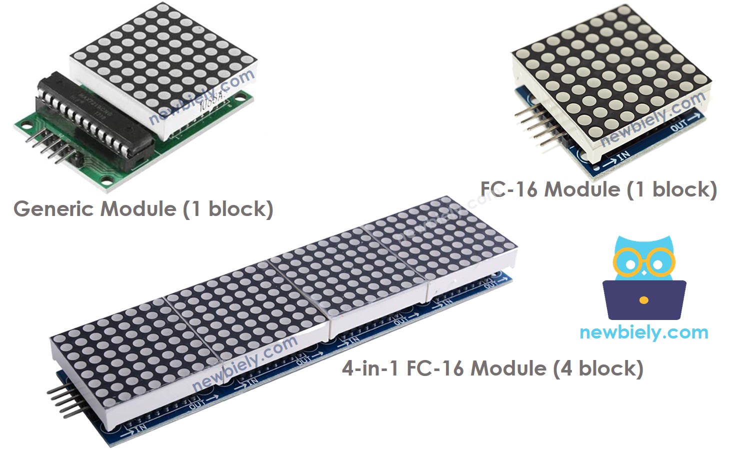
LED Matrix come in many varieties. The MAX7219-based LED matrix is popularly used with ESP8266. It has the following characteristics:
- A single block consists of an 8x8 LED matrix (64 LED) and a MAX7219 driver.
- There are two common types of blocks: generic module and FC-16 module.
- You can either purchase a pre-made multi-block LED Matrix (e.g. 4-in-1, 8-in-1) or wire multiple blocks together to create a LED matrix of your desired size.
- The size of the LED matrix you use must be declared in the ESP8266 code.
The LED Matrix Pinout
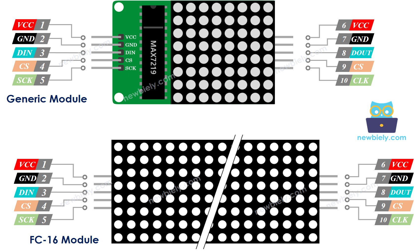
A LED Matrix is made up of one or more blocks. Each block has two sets of pins:
- Input pins group:
- VCC: connected to 5V power supply.
- GND: connected to ground.
- DIN: Data pin, connected to any digital pin of the ESP8266.
- CS: Chip Select, connected to any digital pin of the ESP8266.
- CLK: Clock pin, connected to any digital pin of the ESP8266.
- Output pins group:
- VCC: connects to VCC on the next block.
- GND: connects to GND on the next block.
- DOUT: Data Out, connects to the DIN pin of the next block.
- CS: connects to CS on the next block.
- CLK connects to CLK on the next block.
Wiring Diagram
If the LED matrix is made of a single block:
- Connect the input pins to ESP8266
- Leave the output pins unconnected
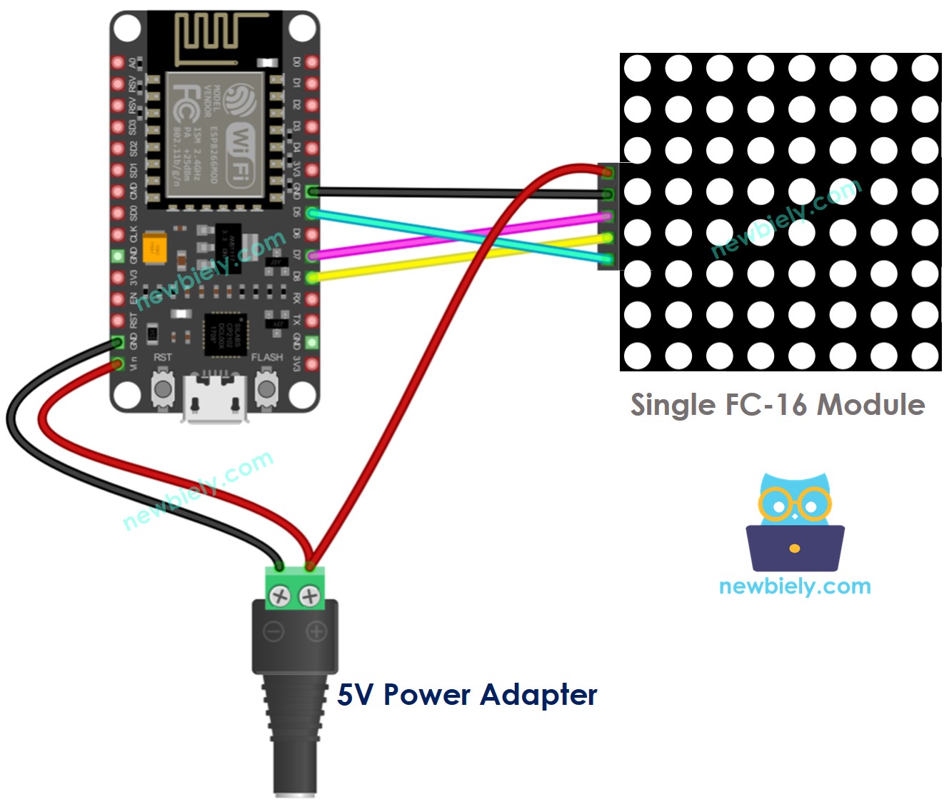
This image is created using Fritzing. Click to enlarge image
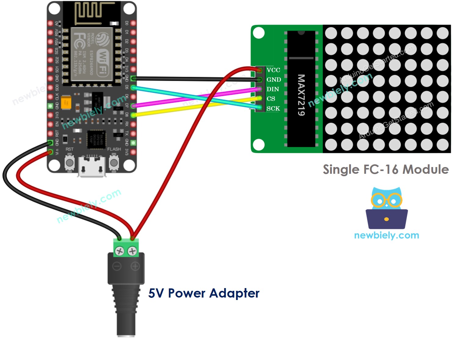
This image is created using Fritzing. Click to enlarge image
If the LED matrix is pre-built of multiple blocks:
- Connect the input pins group to ESP8266
- Leave the output pins group unconnected
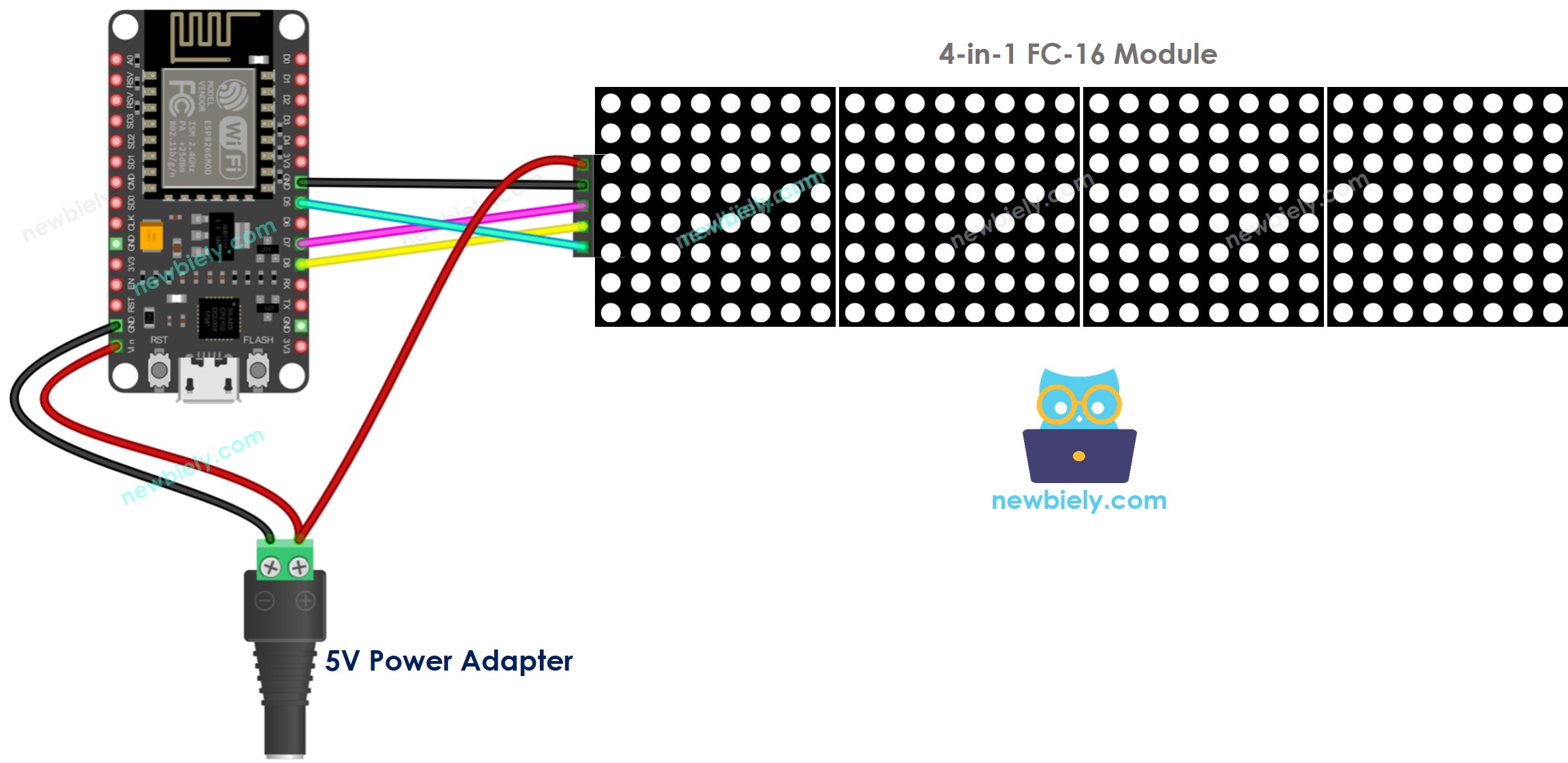
This image is created using Fritzing. Click to enlarge image
If you are making the LED matrix out of multiple blocks:
- Connect the input pins groups of the first block to ESP8266
- Connect the output pins groups of each block to the input pins groups of the subsequent block
- Leave the output pins group of the final block unconnected
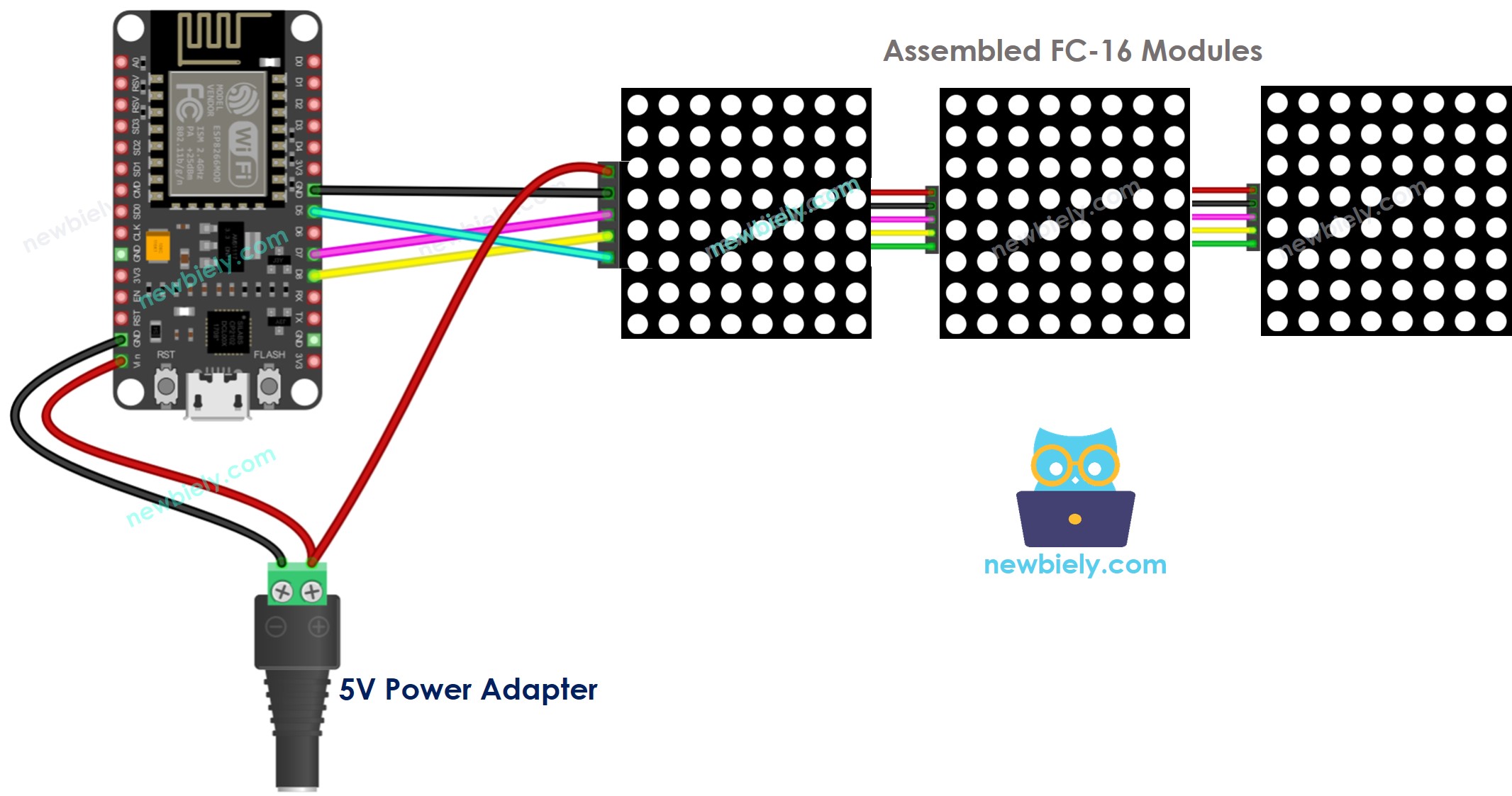
This image is created using Fritzing. Click to enlarge image
See more in ESP8266's pinout and how to supply power to the ESP8266 and other components.
Due to the high current draw of the display (up to 1A at maximum brightness):
- Avoid powering it from the 5V pin of ESP8266.
- Utilize an external 5V power supply instead. ESP8266 and LED matrix can both be powered by a single 5V power adapter.
Since ESP8266 is connected to the LED matrix through SPI pins:
- Pin D5 (SCK) and D7 (MOSI) on the ESP8266 must be utilized. If a different ESP8266 board is being used, consult the official documentation to find the equivalent SPI pins.
- Pin D8 (CS) can be set to any pin on the ESP8266 board.
How To Program For LED Matrix
It is not a simple task to control the LED matrix. Fortunately, libraries are available which make it much easier. Here is a step-by-step guide on how to write ESP8266 code for controlling the LED matrix:
- Incorporate libraries:
- Specify the type of hardware to be utilized: GENERIC_HW or FC16_HW.
- Specify the number of LED blocks used. For instance, a 4-in-1 LED matrix contains 4 blocks.
- Specify the pin that is connected to the CS pin of the LED matrix. For instance, pin D3.
- Generate a MD_Parola object to be used with the LED matrix display.
- Code located in the setup() function:
- Display text, numerical values, and animated effects: refer to the following section.
ESP8266 - LED Matrix Code
This code is suitable for a 32x8 FC-16 LED matrix display consisting of four blocks. It can be easily adapted to other sizes such as 8x8, 16x8, and 64x8.
Detailed Instructions
To get started with ESP8266 on Arduino IDE, follow these steps:
- Check out the how to setup environment for ESP8266 on Arduino IDE tutorial if this is your first time using ESP8266.
- Wire the components as shown in the diagram.
- Connect the ESP8266 board to your computer using a USB cable.
- Open Arduino IDE on your computer.
- Choose the correct ESP8266 board, such as (e.g. NodeMCU 1.0 (ESP-12E Module)), and its respective COM port.
- Connect ESP8266 to the LED matrix as shown in the wiring diagram.
- Connect the ESP8266 to a PC with a USB cable.
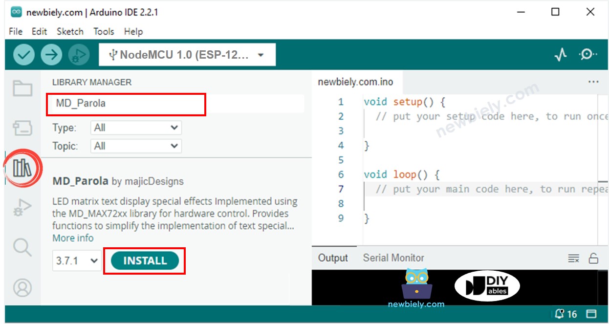
- Click to the Libraries icon on the left bar of the Arduino IDE.
- Search for “MD_Parola”, then locate the MD_Parola library.
- Press the Install button.
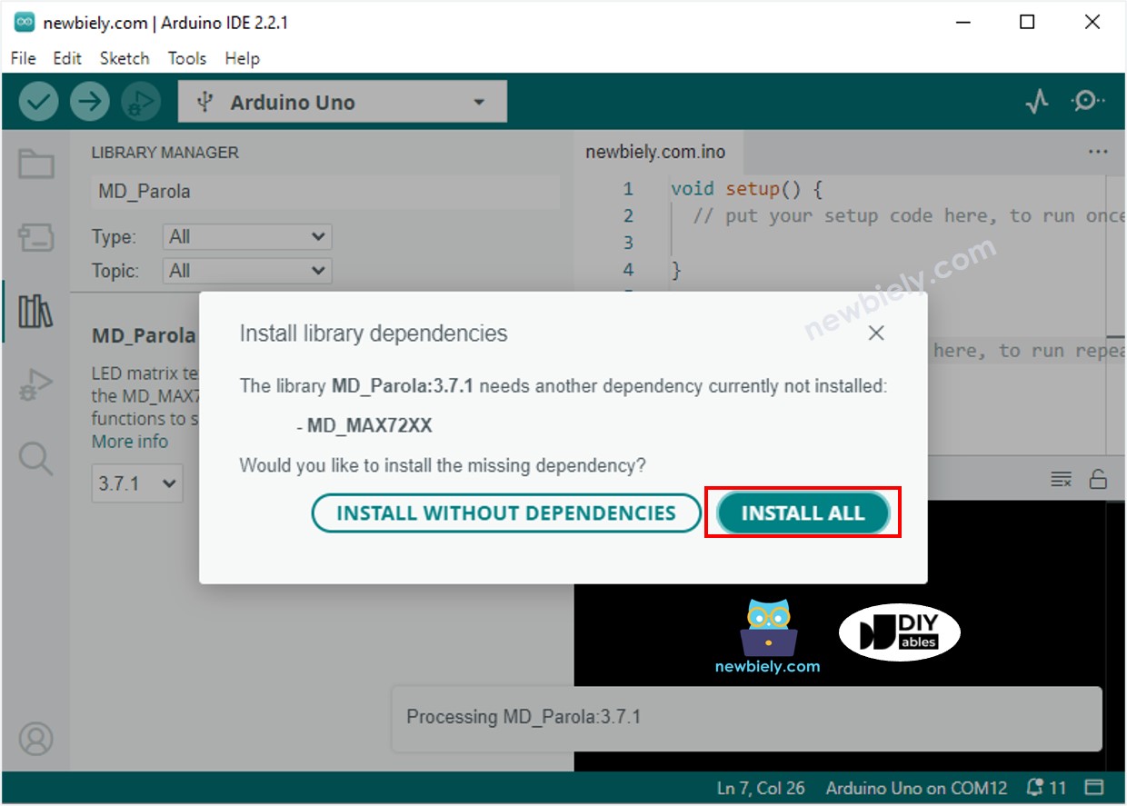
- You will be asked to install the “MD_MAX72XX” library
- Click Install All button to install the dependency.
- The message
- Copy the code and open it with the Arduino IDE.
- Click the Upload button on the Arduino IDE to compile and upload the code to the ESP8266.
- Check out the LED matrix displaying the message.
ESP8266 LED Matrix Code – Scrolling Text
If a message is too lengthy to be displayed on a LED matrix, the scroll text effect can be used. This allows for the entire message to be seen.
This ESP8266 code illustrates how to scroll a message across a LED matrix display.
If you are looking for further text effects, check out the MD_Parola Library Reference.