ESP8266 - Potentiometer Piezo Buzzer
This tutorial instructs you how to use ESP8266 and potentiometer to control piezo buzzer. In detail:
- ESP8266 determines if the potentiometer's analog value is above or below a threshold, and make sound accordingly
- ESP8266 determines if the potentiometer's output voltage is above or below a threshold, and make sound accordingly
- If the potentiometer's output voltage is greater than a threshold, ESP8266 can also play a melody of a song
Hardware Preparation
Or you can buy the following kits:
| 1 | × | DIYables Sensor Kit (18 sensors/displays) |
Additionally, some of these links are for products from our own brand, DIYables .
Overview of Piezo Buzzer and Potentiometer
If you are unfamiliar with the pinout, operation, and programming of piezo buzzers and potentiometers, the following tutorials can help:
Wiring Diagram
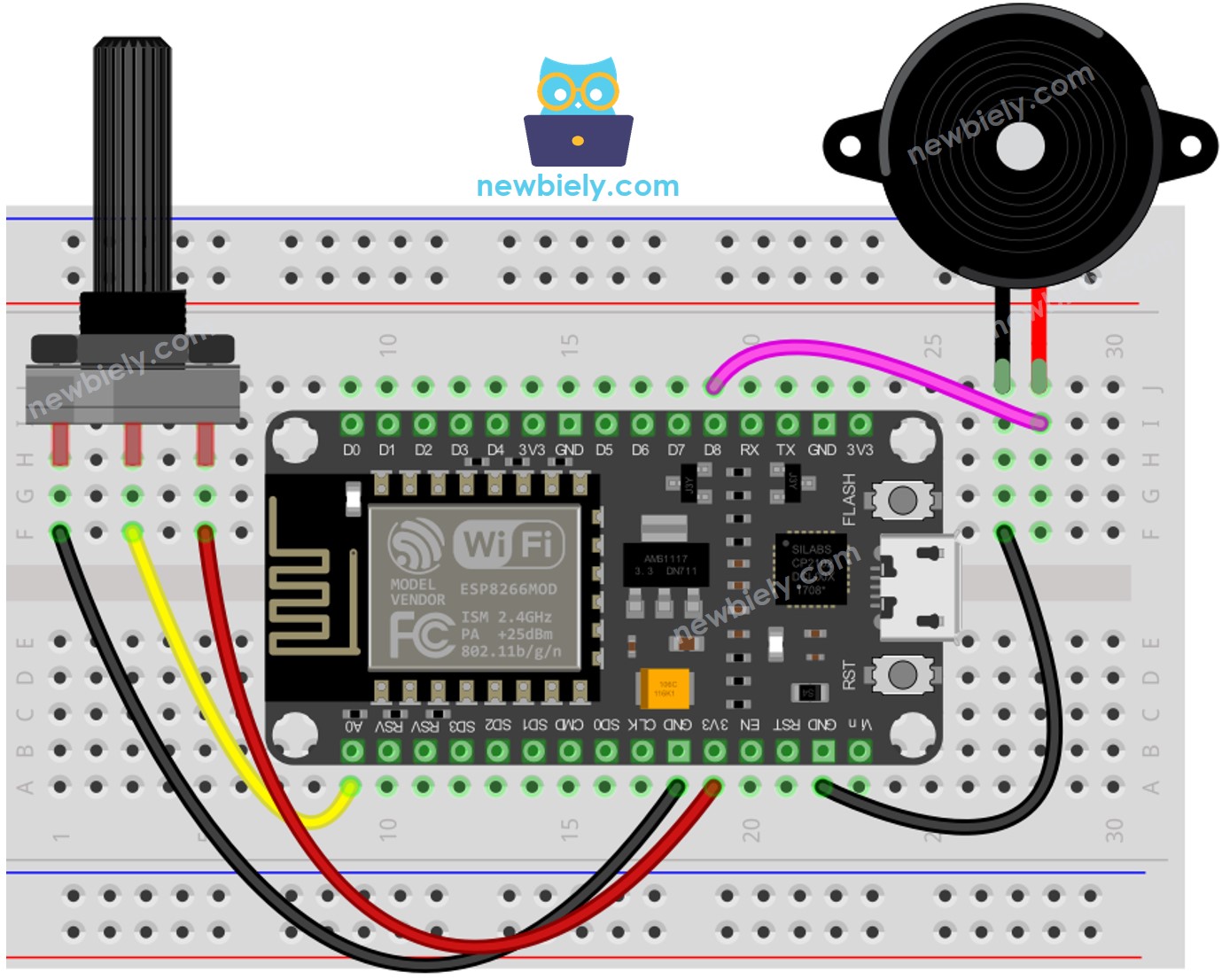
This image is created using Fritzing. Click to enlarge image
See more in ESP8266's pinout and how to supply power to the ESP8266 and other components.
ESP8266 Code - Simple Sound - Analog Threshold
Detailed Instructions
To get started with ESP8266 on Arduino IDE, follow these steps:
- Check out the how to setup environment for ESP8266 on Arduino IDE tutorial if this is your first time using ESP8266.
- Wire the components as shown in the diagram.
- Connect the ESP8266 board to your computer using a USB cable.
- Open Arduino IDE on your computer.
- Choose the correct ESP8266 board, such as (e.g. NodeMCU 1.0 (ESP-12E Module)), and its respective COM port.
- Connect the ESP8266 NodeMCU to the computer using a USB cable.
- Open the Arduino IDE, pick the correct board and port.
- Copy the code and open it in the Arduino IDE.
- Click the Upload button in the Arduino IDE to send the code to the ESP8266.
- Turn the potentiometer.
- Hear the sound coming from the piezo buzzer.
Code Explanation
Check out the line-by-line explanation contained in the comments of the source code!
ESP8266 Code - Simple Sound - Voltage Threshold
The analog value of a Potentiometer is changed to a voltage value,. Then this voltage is compared to a voltage threshold,. Which will activate the Piezo Buzzer if the threshold is exceeded.
ESP8266 Code - Melody - Voltage Threshold
Detailed Instructions
- Wire the components as shown in the diagram.
- Connect the ESP8266 board to your computer using a USB cable.
- Open Arduino IDE on your computer.
- Choose the correct ESP8266 board, such as (e.g. NodeMCU 1.0 (ESP-12E Module)), and its respective COM port.
- Copy the code and open it with the Arduino IDE.
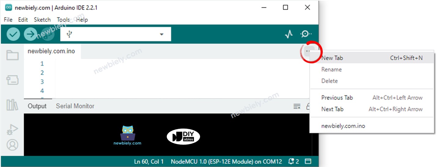
- Create the pitches.h file On Arduino IDE by:
- Either click on the button just below the serial monitor icon and choose New Tab, or use Ctrl+Shift+N keys.
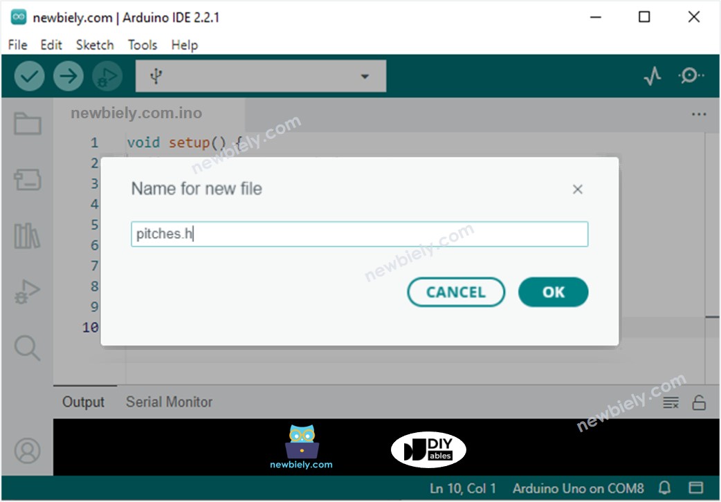
- Give file's name pitches.h and click OK button
- Copy the below code and paste it to the created pitches.h file.
- Click the Upload button on the Arduino IDE to compile and upload the code to the ESP8266.
- Turn the potentiometer.
- Listen to the tune of the piezo buzzer.
Code Explanation
Check out the line-by-line explanation contained in the comments of the source code!