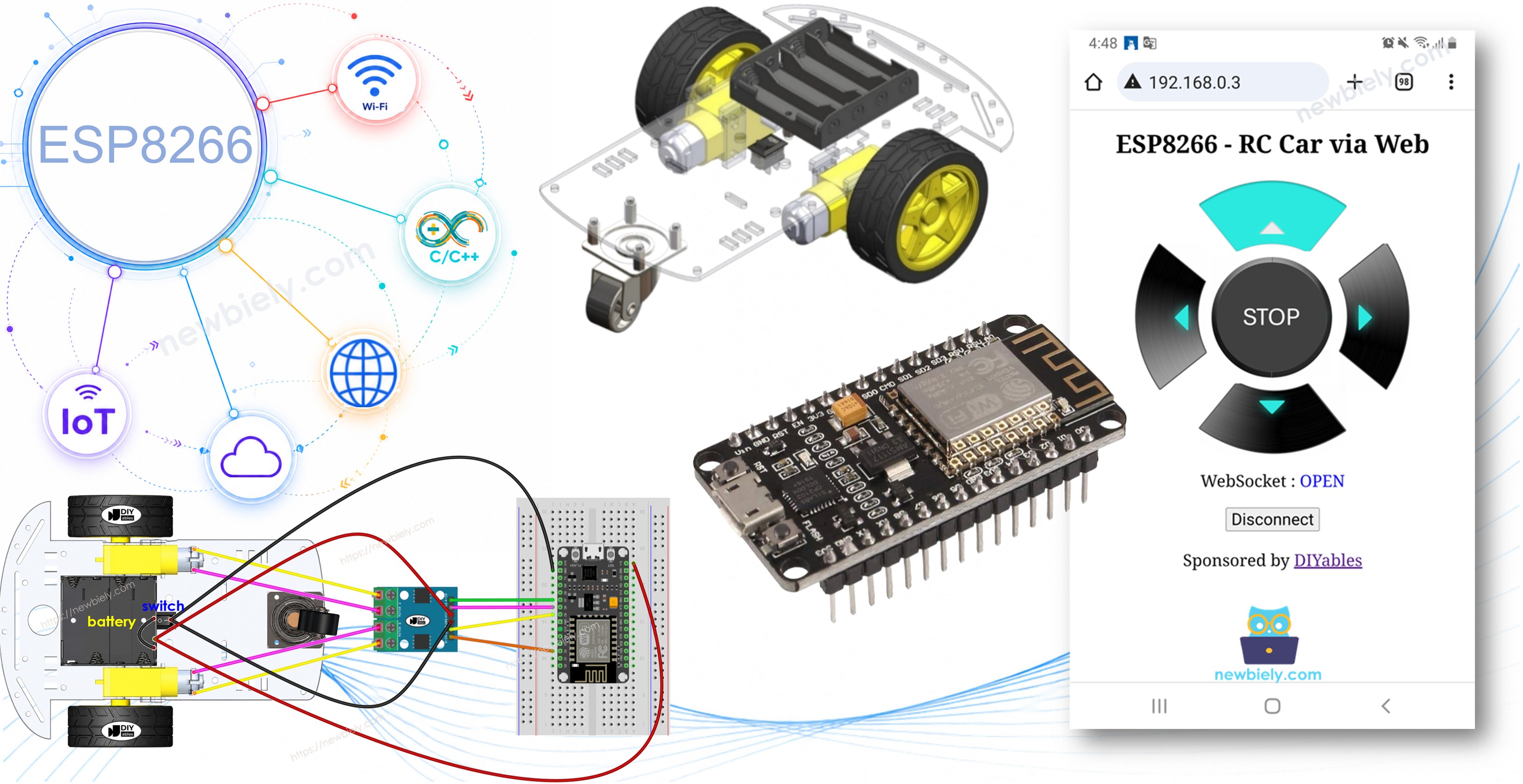
This tutorial instructs you how to use the ESP8266 to wirelessly control a robot car from a Web browser on your smartphone or PC using WiFi. The control is facilitated through a graphical web user interface using something called WebSocket, allowing for smooth and dynamic control of the car.
Disclosure: Some of the links provided in this section are Amazon affiliate links. We may receive a commission for any purchases made through these links at no additional cost to you. Additionally, some of these links are for products from our own brand, DIYables .
Overview of 2WD RC Car and WebSocket
Now, why go for WebSocket? Here's the scoop:
Without WebSocket, changing the car's direction would require reloading the page every time. Not ideal!
However, with WebSocket, we establish a special connection between the webpage and the ESP8266. This enables sending commands to the ESP8266 in the background, without needing to reload the page. The result? The robot car moves seamlessly and in real-time. Pretty cool, right?
In a nutshell, the WebSocket connection enables the smooth, real-time control of the robot.
We have specific tutorials about 2WD RC Car and WebSocket. Each tutorial contains detailed information and step-by-step instructions about hardware pinout, working principle, wiring connection to ESP8266, ESP8266 code... Learn more about them at the following links:
The ESP8266 code creates both a web server and a WebSocket Server. Here's how it works:
When you enter the ESP8266's IP address in a web browser, it requests the webpage (User Interface) from the ESP8266.
The ESP8266's web server responds by sending the webpage's content (HTML, CSS, JavaScript).
Your web browser then displays the webpage.
The JavaScript code within the webpage establishes a WebSocket connection to the WebSocket server on the ESP8266.
Once this WebSocket connection is established, if you press/release the buttons on the webpage, the JavaScript code quietly sends the commands to the ESP8266 through this WebSocket connection in the background.
The WebSocket server on the ESP8266, upon receiving the commands, controls the robot car accordingly.
The below table show commands list that the webpage sends to ESP8266 based on the user's actions:
User's Action
Button
Command
Car Action
PRESS
UP
1
MOVE FORWARD
PRESS
DOWN
2
MOVE BACKWARD
PRESS
LEFT
4
TURN LEFT
PRESS
RIGHT
8
TURN RIGHT
PRESS
STOP
0
STOP
RELEASE
UP
0
STOP
RELEASE
DOWN
0
STOP
RELEASE
LEFT
0
STOP
RELEASE
RIGHT
0
STOP
RELEASE
STOP
0
STOP
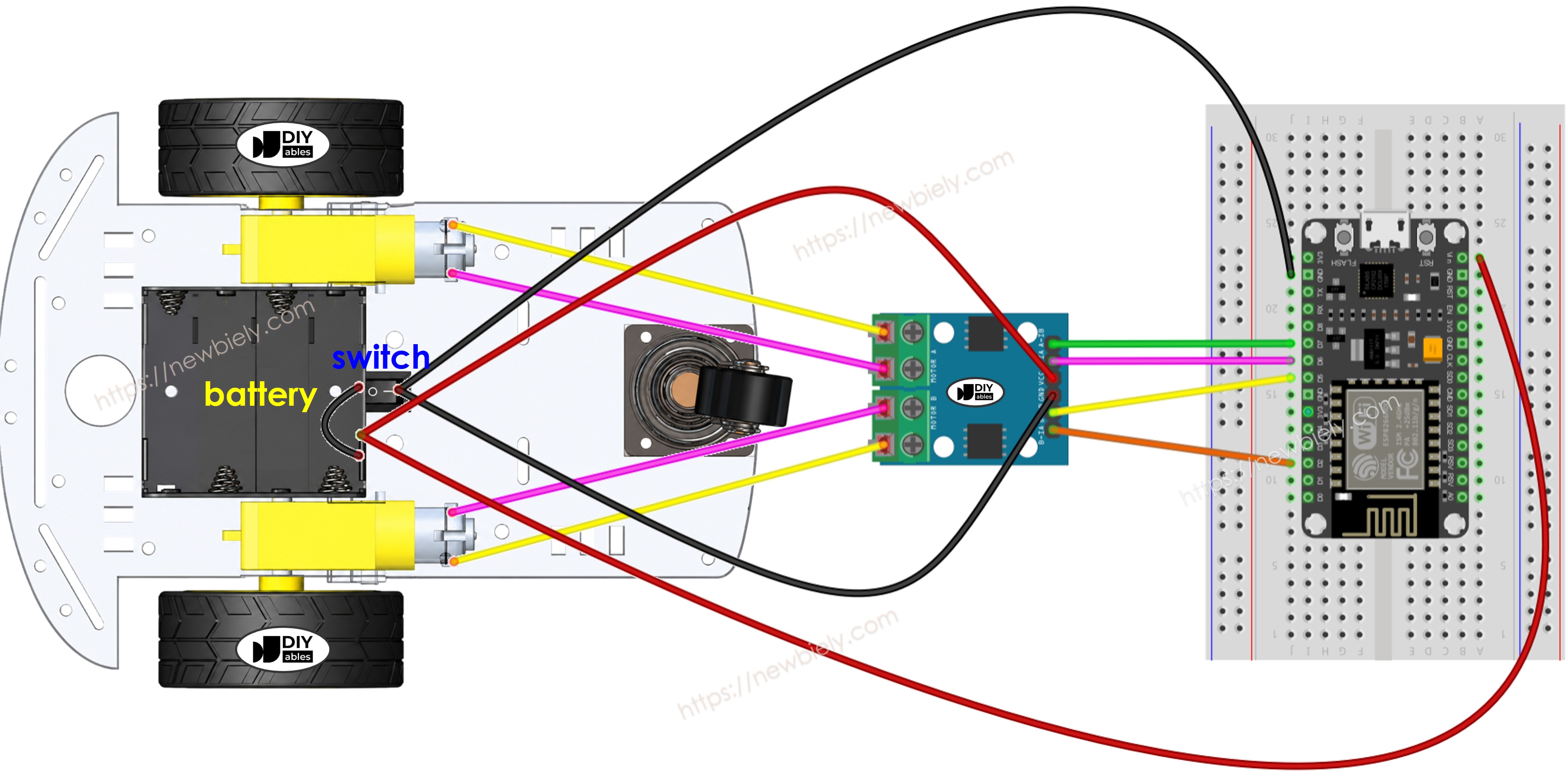
Wiring Diagram between 2WD RC Car and ESP8266
This image is created using Fritzing. Click to enlarge image
The L9110S module powers the motors directly from its VCC and GND pins and does not have an onboard 5V regulator. This means you can power everything from a single power source — four 1.5V AA batteries (totaling 6V). Here's how to do it:
Connect the 6V battery to the VCC and GND pins of the L9110S module to power the motors.
Connect the same 6V battery to the Vin and GND pins of the ESP8266 to power the ESP8266 board.
Make sure the L9110S module and the ESP8266 share a common GND.
Unlike the L298N, the L9110S has no ENA/ENB enable jumpers and no 12V screw terminal, so the wiring is simpler.
Since the 2WD RC car has an on/off switch, you can optionally connect the battery via the switch to enable turning on/off power for the car. If you want to make it simple, just ignore the switch.
ESP8266 Code
The webpage's content (HTML, CSS, JavaScript) are stored separately on an index.h file. So, we will have two code files on Arduino IDE:
An .ino file that is ESP8266 code, which creates a web server and WebSocket Server, and controls car
An .h file, which contains the webpage's content.
Detailed Instructions
To get started with ESP8266 on Arduino IDE, follow these steps:
Connect the ESP8266 board to your computer using a USB cable.
Open Arduino IDE on your computer.
Choose the correct ESP8266 board, such as (e.g. NodeMCU 1.0 (ESP-12E Module)), and its respective COM port.
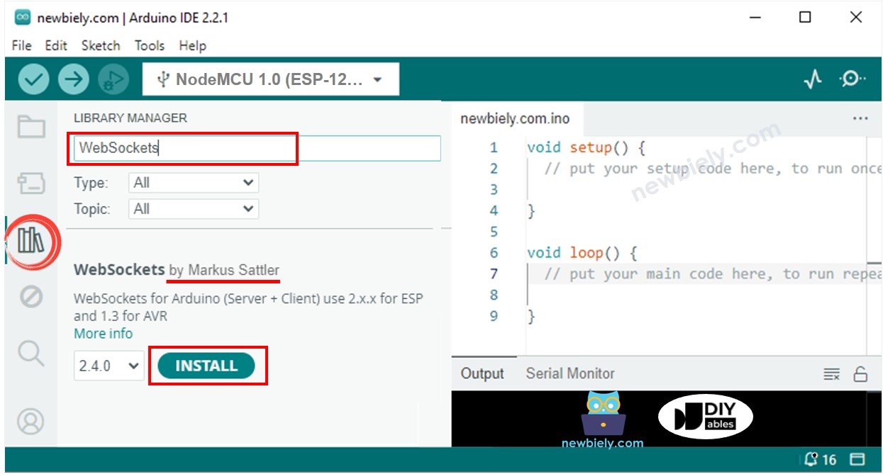
Open the Library Manager by clicking on the Library Manager icon on the left navigation bar of Arduino IDE.
Search “WebSockets”, then find the WebSockets created by Markus Sattler.
Click Install button to install WebSockets library.
On Arduino IDE, create new sketch, Give it a name, for example, newbiely.com.ino
Copy the below code and open with Arduino IDE
/* * This ESP8266 NodeMCU code was developed by newbiely.com * * This ESP8266 NodeMCU code is made available for public use without any restriction * * For comprehensive instructions and wiring diagrams, please visit: * https://newbiely.com/tutorials/esp8266/esp8266-controls-car-via-web */#include <ESP8266WiFi.h>#include <ESP8266WebServer.h>#include"index.h"#define CMD_STOP 0#define CMD_FORWARD 1#define CMD_BACKWARD 2#define CMD_LEFT 4#define CMD_RIGHT 8#define MOTOR_A_IA_PIN D2 // The ESP8266 pin connected to the A-IA pin of the L9110S (Motor A)#define MOTOR_A_IB_PIN D5 // The ESP8266 pin connected to the A-IB pin of the L9110S (Motor A)#define MOTOR_B_IA_PIN D6 // The ESP8266 pin connected to the B-IA pin of the L9110S (Motor B)#define MOTOR_B_IB_PIN D7 // The ESP8266 pin connected to the B-IB pin of the L9110S (Motor B)const char* ssid = "YOUR_WIFI_SSID"; // CHANGE ITconst char* password = "YOUR_WIFI_PASSWORD"; // CHANGE ITESP8266WebServer server(80); // Web server on port 80DIYables_ESP32_WebSocket* webSocket;void webSocketEvent(uint8_t num, WStype_t type, uint8_t* payload, size_t length) {switch (type) {case WStype_DISCONNECTED:Serial.printf("[%u] Disconnected!\n", num);break;case WStype_CONNECTED: {IPAddress ip = webSocket.remoteIP(num);Serial.printf("[%u] Connected from %d.%d.%d.%d\n", num, ip[0], ip[1], ip[2], ip[3]); }break;case WStype_TEXT://Serial.printf("[%u] Received text: %s\n", num, payload);String angle = String((char*)payload);intcommand = angle.toInt();Serial.print("command: ");Serial.println(command);switch (command) {case CMD_STOP:Serial.println("Stop"); CAR_stop();break;case CMD_FORWARD:Serial.println("Move Forward"); CAR_moveForward();break;case CMD_BACKWARD:Serial.println("Move Backward"); CAR_moveBackward();break;case CMD_LEFT:Serial.println("Turn Left"); CAR_turnLeft();break;case CMD_RIGHT:Serial.println("Turn Right"); CAR_turnRight();break;default:Serial.println("Unknown command"); }break; }}voidsetup() {Serial.begin(9600);pinMode(MOTOR_A_IA_PIN, OUTPUT);pinMode(MOTOR_A_IB_PIN, OUTPUT);pinMode(MOTOR_B_IA_PIN, OUTPUT);pinMode(MOTOR_B_IB_PIN, OUTPUT);// Connect to Wi-FiWiFi.begin(ssid, password);while (WiFi.status() != WL_CONNECTED) {delay(1000);Serial.println("Connecting to WiFi..."); }Serial.println("Connected to WiFi");// Initialize WebSocket server webSocket.begin(); webSocket.onEvent(webSocketEvent);// Serve a basic HTML page with JavaScript to create the WebSocket connection server.on("/", HTTP_GET, []() {Serial.println("Web Server: received a web page request");String html = HTML_CONTENT; // Use the HTML content from the servo_html.h file server.send(200, "text/html", html); }); server.begin(); Serial.print("ESP8266 Web Server's IP address: "); Serial.println(WiFi.localIP());}void loop() {// Handle client requests server.handleClient();// Handle WebSocket events webSocket.loop();// TO DO: Your code here}void CAR_moveForward() {digitalWrite(MOTOR_A_IA_PIN, HIGH);digitalWrite(MOTOR_A_IB_PIN, LOW);digitalWrite(MOTOR_B_IA_PIN, HIGH);digitalWrite(MOTOR_B_IB_PIN, LOW);}void CAR_moveBackward() {digitalWrite(MOTOR_A_IA_PIN, LOW);digitalWrite(MOTOR_A_IB_PIN, HIGH);digitalWrite(MOTOR_B_IA_PIN, LOW);digitalWrite(MOTOR_B_IB_PIN, HIGH);}void CAR_turnLeft() {digitalWrite(MOTOR_A_IA_PIN, HIGH);digitalWrite(MOTOR_A_IB_PIN, LOW);digitalWrite(MOTOR_B_IA_PIN, LOW);digitalWrite(MOTOR_B_IB_PIN, LOW);}void CAR_turnRight() {digitalWrite(MOTOR_A_IA_PIN, LOW);digitalWrite(MOTOR_A_IB_PIN, LOW);digitalWrite(MOTOR_B_IA_PIN, HIGH);digitalWrite(MOTOR_B_IB_PIN, LOW);}void CAR_stop() {digitalWrite(MOTOR_A_IA_PIN, LOW);digitalWrite(MOTOR_A_IB_PIN, LOW);digitalWrite(MOTOR_B_IA_PIN, LOW);digitalWrite(MOTOR_B_IB_PIN, LOW);}
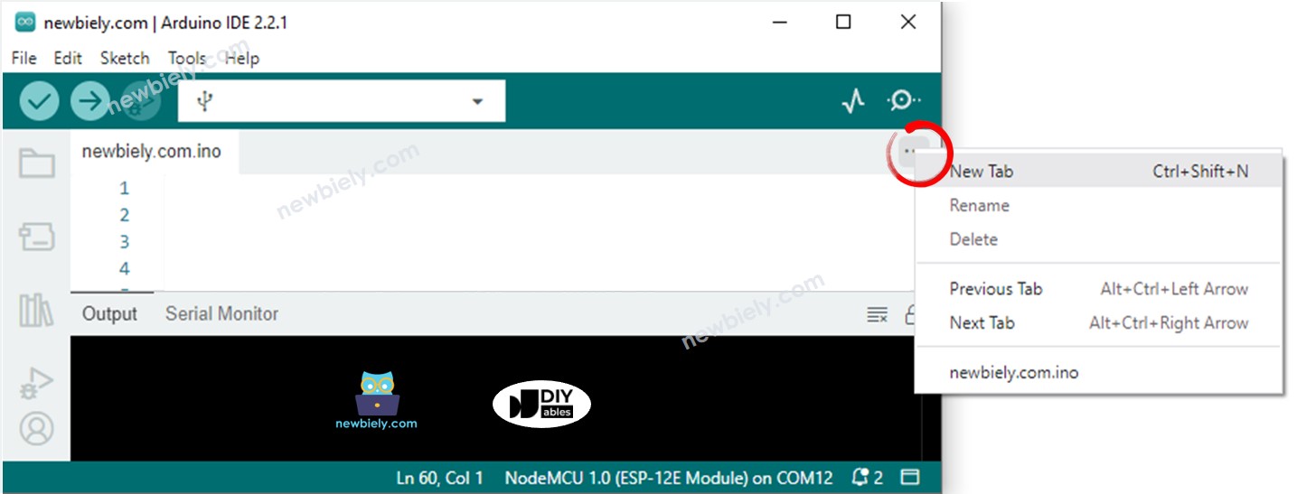
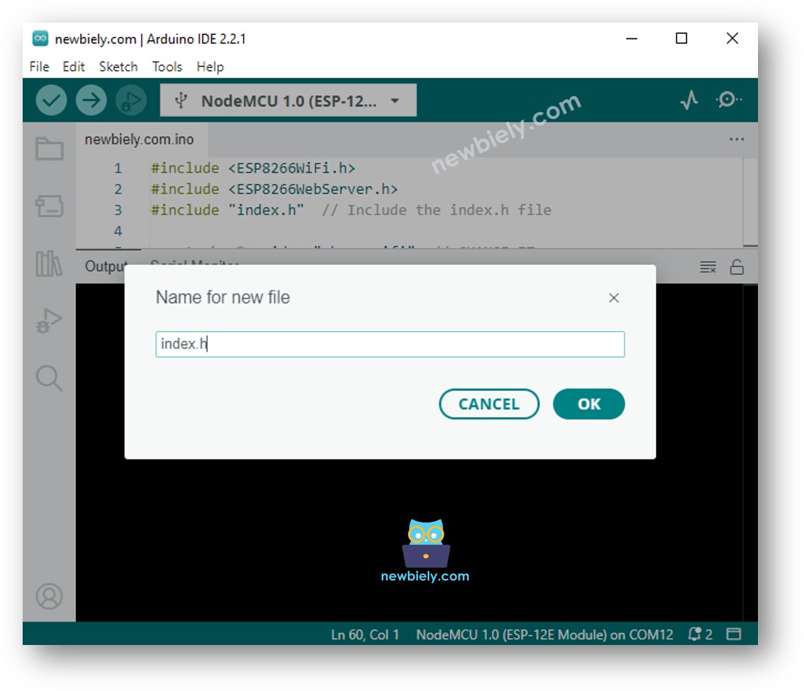
Create the index.h file On Arduino IDE by:
Either click on the button just below the serial monitor icon and choose New Tab, or use Ctrl+Shift+N keys.
Now you have the code in two files: newbiely.com.ino and index.h
Click Upload button on Arduino IDE to upload code to ESP8266
Open the Serial Monitor
Check out the result on Serial Monitor.
Newbiely | Arduino IDE 2.3.8
──
☐
✕
File
Edit
Sketch
Tools
Help
Nodemcu 1.0 (ESP-12E Module)
Newbiely.ino
···
8Serial.println("Hello World!");
Output
Serial Monitor
Message (Enter to send message to 'Nodemcu 1.0 (ESP-12E Module)' on 'COM15')
New Line
9600 baud
Connecting to WiFi...
Connected to WiFi
ESP8266 Web Server's IP address IP address: 192.168.0.5
Ln 11, Col 1
Nodemcu 1.0 (ESP-12E Module) on COM15
2
Take note of the IP address displayed, and enter this address into the address bar of a web browser on your smartphone or PC.
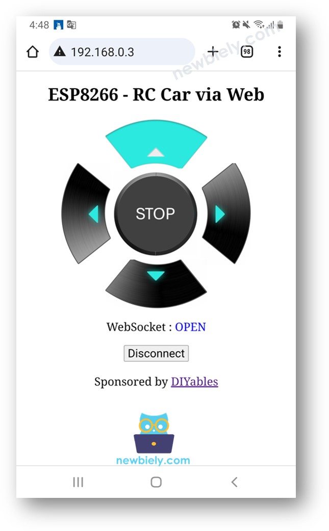
You will see the webpage it as below:
The JavaScript code of the webpage automatically creates the WebSocket connection to ESP8266.
Now you can control the car to turn left/right, move forward/backward via the web interface.
To save the memory of ESP8266, the images of the control buttons are NOT stored on ESP8266. Instead, they are stored on the internet, so, your phone or PC need to have internet connection to load images for the web control page.
※ NOTE THAT:
If you modify the HTML content in the index.h and does not touch anything in newbiely.com.ino file, when you compile and upload code to ESP8266, Arduino IDE will not update the HTML content.
To make Arduino IDE update the HTML content in this case, make a change in the newbiely.com.ino file (e.g. adding empty line, add a comment....)
Line-by-line Code Explanation
The above ESP8266 code contains line-by-line explanation. Please read the comments in the code!
Please feel free to share the link of this tutorial. However, Please do not use our content on any other websites. We invested a lot of effort and time to create the content, please respect our work!