ESP8266 - OLED Clock
This tutorial instructs you how to create an OLED clock by using ESP8266, RTC module and OLED display. The tutorial provides instructions for both DS3231 and DS1307 RTC modules. In detail:
- ESP8266 obtains the hour, minute, and second from a DS3231 RTC module and displaying it on an OLED
- ESP8266 obtains the hour, minute, and second from a DS1307 RTC module and displaying it on an OLED
You can choose one of two RTC modules: DS3231 and DS1307. For more information, please refer to DS3231 vs DS1307.
Hardware Preparation
Or you can buy the following kits:
| 1 | × | DIYables Sensor Kit (18 sensors/displays) |
Additionally, some of these links are for products from our own brand, DIYables .
Buy Note: If you want a bigger OLED display, use the 2.42 inch OLED Display 128x64 .
Overview of OLED, DS3231 and DS1307 RTC module
If you are unfamiliar with OLED, DS3231 and DS1307 (pinout, functionality, programming ...), the following tutorials can help you:
Install OLED and RTC Libraries
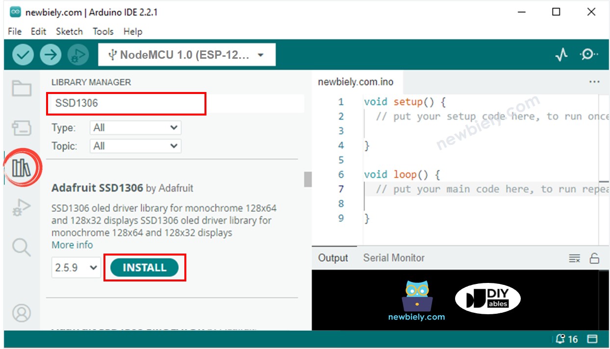
- Click to the Libraries icon on the left bar of the Arduino IDE.
- Search for “SSD1306” and locate the SSD1306 library from Adafruit.
- Then, press the Install button to complete the installation.
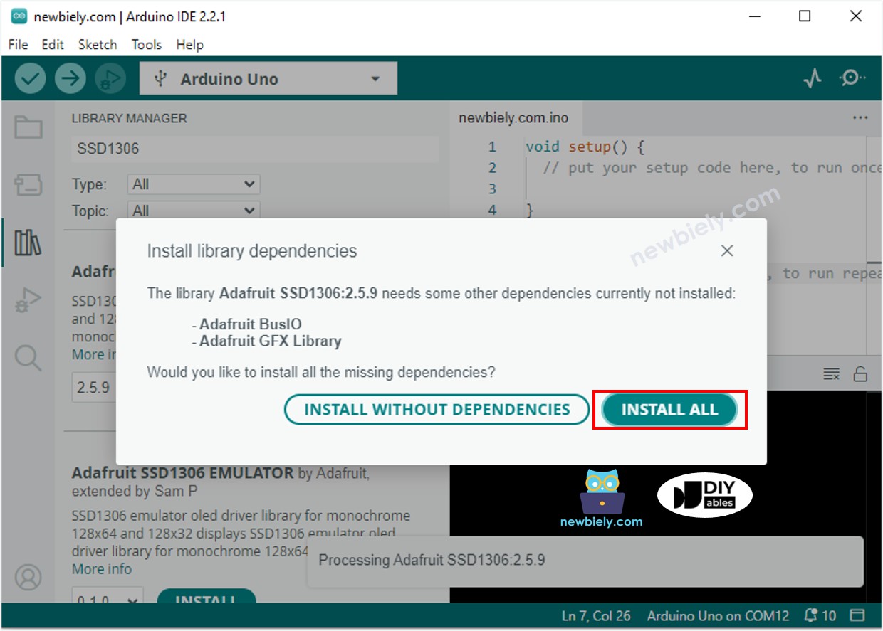
- You will be prompted to install additional library dependencies.
- To install them all at once, click the Install All button.
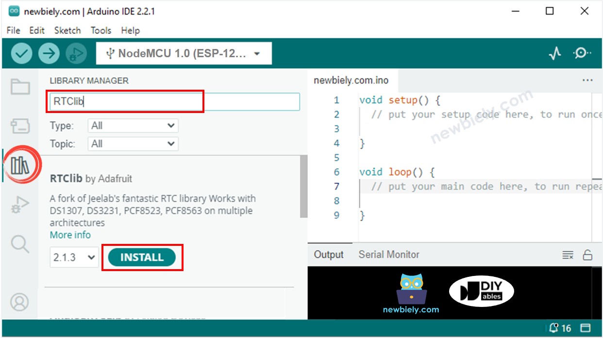
- Search for “RTClib” and locate the RTC library from Adafruit. This library is compatible with both DS3231 and DS1307.
- Press the Install button to install the RTC library.
Reading time from DS3231 RTC module and display it on OLED
Wiring Diagram
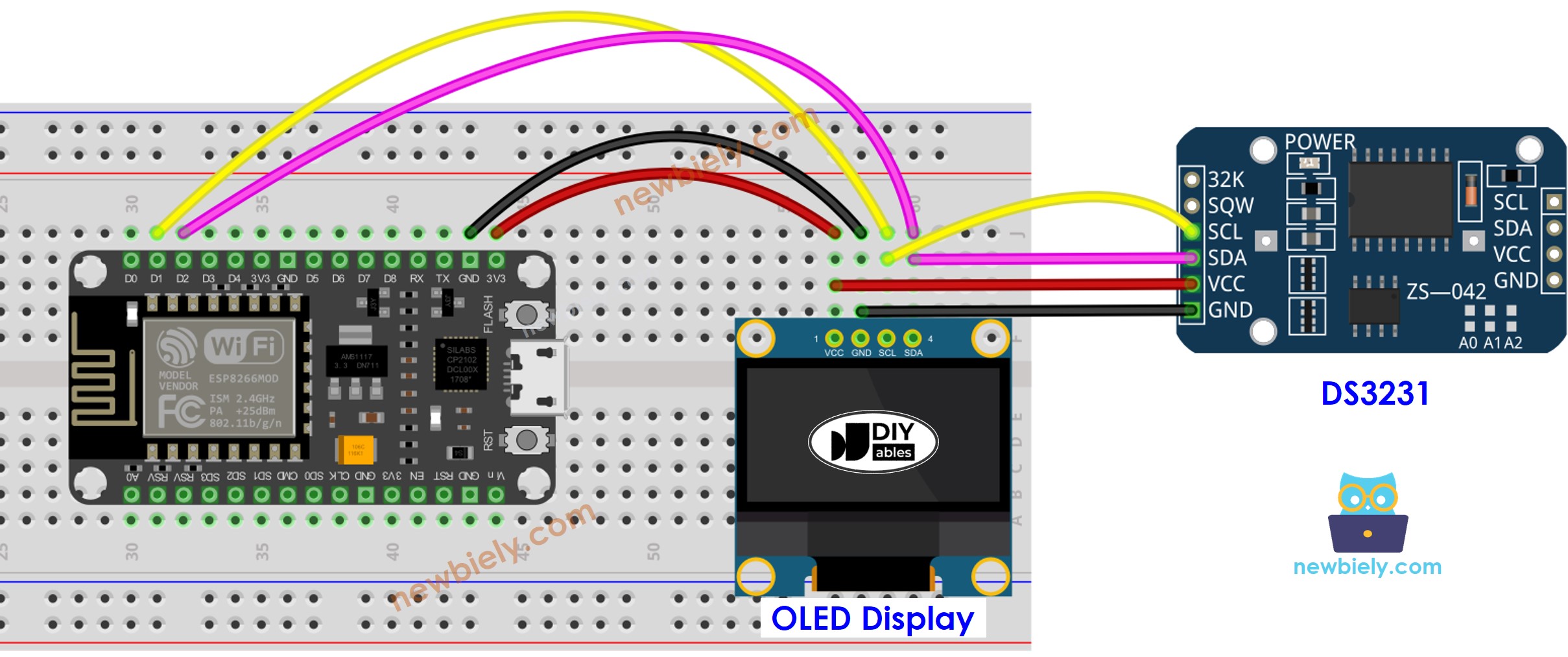
This image is created using Fritzing. Click to enlarge image
ESP8266 Code - DS3231 and OLED
Detailed Instructions
To get started with ESP8266 on Arduino IDE, follow these steps:
- Check out the how to setup environment for ESP8266 on Arduino IDE tutorial if this is your first time using ESP8266.
- Wire the components as shown in the diagram.
- Connect the ESP8266 board to your computer using a USB cable.
- Open Arduino IDE on your computer.
- Choose the correct ESP8266 board, such as (e.g. NodeMCU 1.0 (ESP-12E Module)), and its respective COM port.
- Copy the code and open it with the Arduino IDE.
- Click the Upload button in the Arduino IDE to send the code to the ESP8266.
- Place the sensor in hot and cold water, or hold it in your hand.
- Check out the outcome on the OLED.
Reading time from DS1307 RTC module and display it on OLED
Wiring Diagram
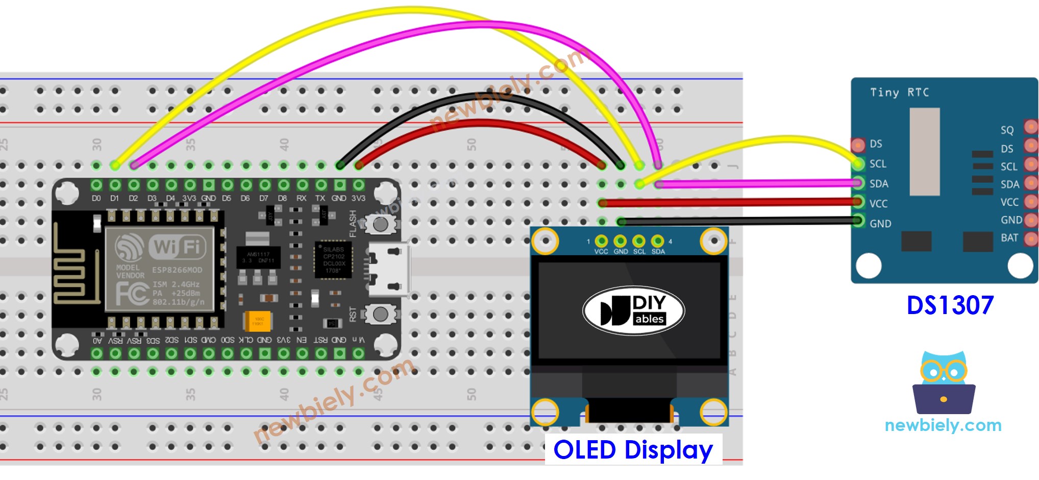
This image is created using Fritzing. Click to enlarge image
See more in ESP8266's pinout and how to supply power to the ESP8266 and other components.
ESP8266 Code - DS1307 and OLED
Detailed Instructions
- Wire the components as shown in the diagram.
- Connect the ESP8266 board to your computer using a USB cable.
- Open Arduino IDE on your computer.
- Choose the correct ESP8266 board, such as (e.g. NodeMCU 1.0 (ESP-12E Module)), and its respective COM port.
- Copy the code and open it in the Arduino IDE.
- Click the Upload button to transfer the code to the ESP8266.
- Place the sensor in hot and cold water or hold it in your hand.
- Check out the result on the OLED.