ESP8266 - 74HC595 4-Digit 7-Segment Display
Let's get your ESP8266 up and running with a 4-digit 7-segment display powered by a 74HC595 shift register. The ESP8266 is a compact, affordable Wi-Fi microcontroller - perfect for lightweight IoT projects that need a local readout.
Here is what we will cover:
How to wire the 74HC595 display module to the ESP8266.
How to display integers and floating-point numbers.
How to show text and temperature with a degree symbol.
How to present time in HH.MM format with a blinking dot.
Or you can buy the following kits:
Disclosure: Some of the links provided in this section are Amazon affiliate links. We may receive a commission for any purchases made through these links at no additional cost to you.
Additionally, some of these links are for products from our own brand,
DIYables .
Four 7-segment digits driven by a 74HC595 shift register. Only 3 data pins needed from the microcontroller. The register takes serial data, converts it to parallel output for the segments, and the library handles the multiplexing between digits. You call print() once, then keep calling loop() to maintain the display.
| Function | Pin | Description |
|---|
| SCLK (SH_CP) | Serial Clock | Clocks data into the shift register |
| RCLK (ST_CP) | Register Clock | Latches data to the output pins |
| DIO (DS) | Data Input | Serial data line |
| VCC | Power | 3.3V or 5V |
| GND | Ground | Common ground |
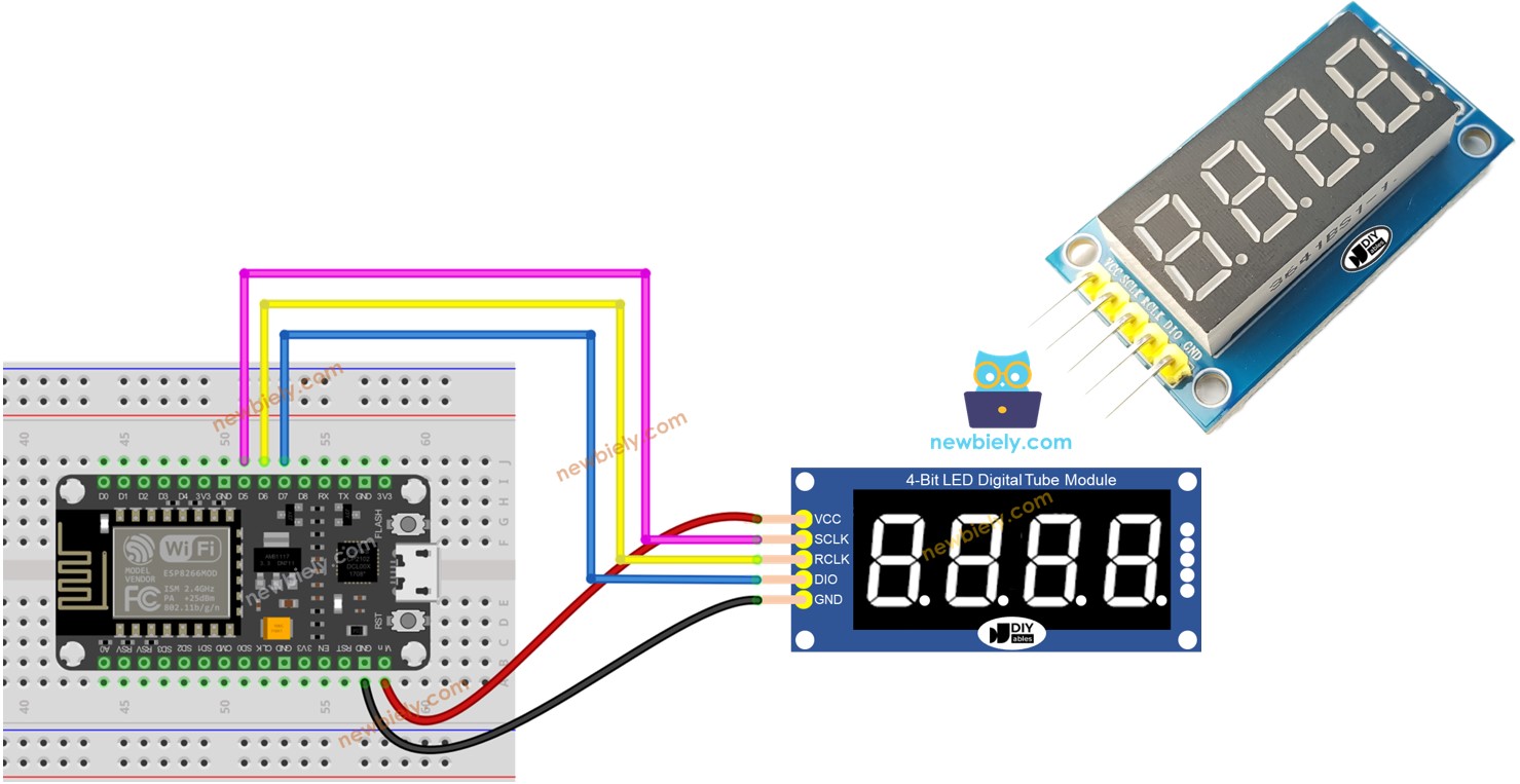
Connect the display module to the ESP8266 NodeMCU:
SCLK to D5 (GPIO14)
RCLK to D6 (GPIO12)
DIO to D7 (GPIO13)
VCC to 3.3V
GND to GND
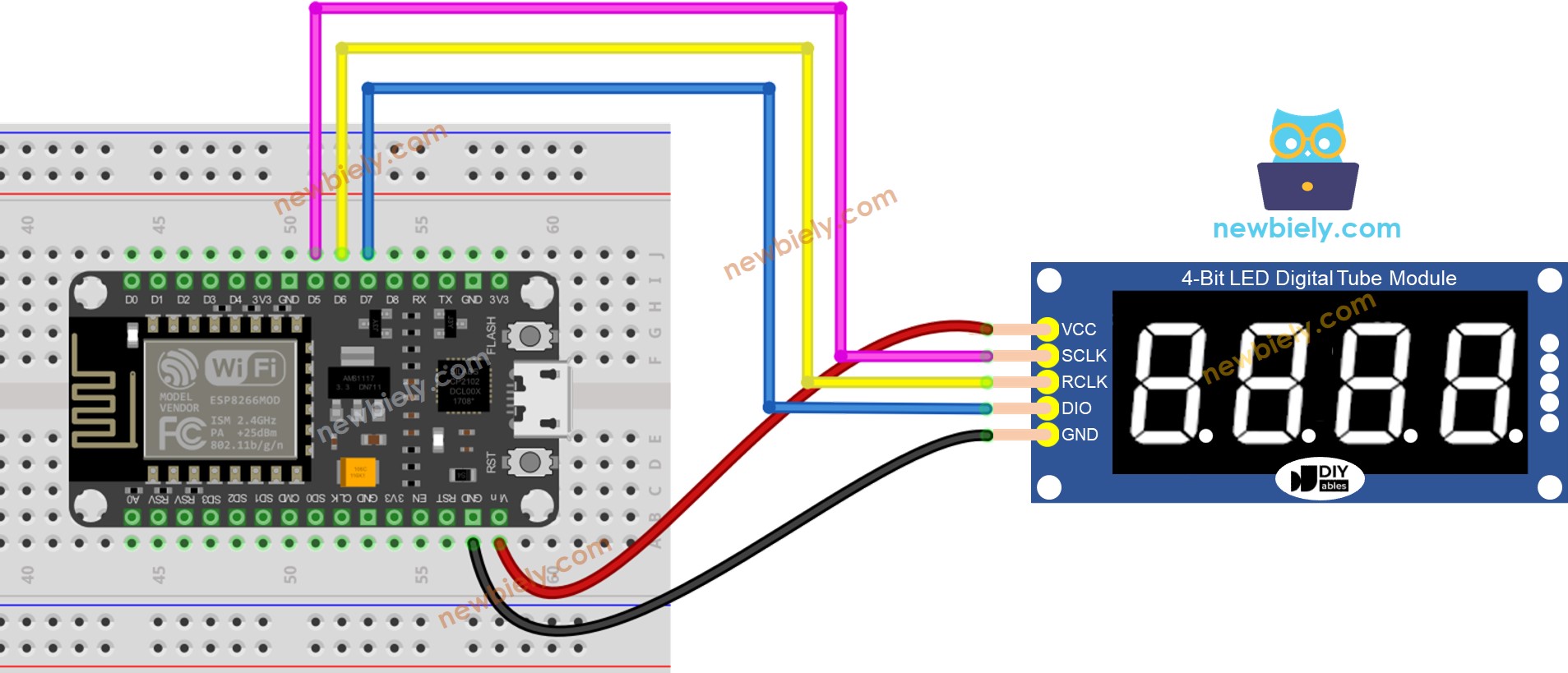
This image is created using Fritzing. Click to enlarge image
See more in ESP8266's pinout and how to supply power to the ESP8266 and other components.
Connect the ESP8266 to your computer with a USB cable.
Open Arduino IDE. Select NodeMCU 1.0 (ESP-12E Module) as the board and pick the right port.
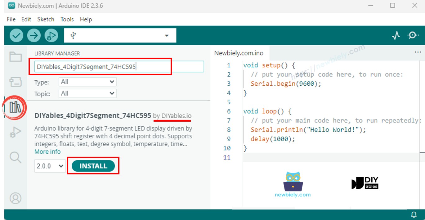
Head to the Libraries section on the left.
Look up "DIYables_4Digit7Segment_74HC595" and find the DIYables library.
Tap Install. Select version 2.0.0 or later.
The library ships with everything it needs - no extra dependencies.
The shortest sketch to see results:
#include <DIYables_4Digit7Segment_74HC595.h>
#define SCLK_PIN D5
#define RCLK_PIN D6
#define DIO_PIN D7
DIYables_4Digit7Segment_74HC595 display(SCLK_PIN, RCLK_PIN, DIO_PIN);
void setup() {
display.begin();
display.print(1234);
}
void loop() {
display.loop();
}
Set up with begin(), set the display value with print(), and keep display.loop() running. Use display.delay() instead of delay() so the display stays refreshed.
Cycles through integers and shows zero-padding.
#include <DIYables_4Digit7Segment_74HC595.h>
#define SCLK_PIN 5
#define RCLK_PIN 6
#define DIO_PIN 7
DIYables_4Digit7Segment_74HC595 display(SCLK_PIN, RCLK_PIN, DIO_PIN);
int numbers[] = {0, 42, 1234, -5, -123, 9999};
int numCount = 6;
int currentIndex = 0;
bool showZeroPad = false;
unsigned long lastChange = 0;
void setup() {
Serial.begin(9600);
display.begin();
Serial.println("4-Digit 7-Segment 74HC595 - Integer Example");
}
void loop() {
display.loop();
if (millis() - lastChange >= 2000) {
lastChange = millis();
if (!showZeroPad) {
display.print(numbers[currentIndex]);
Serial.print("Displaying: ");
Serial.println(numbers[currentIndex]);
currentIndex++;
if (currentIndex >= numCount) {
currentIndex = 0;
showZeroPad = true;
}
} else {
display.print(42, true);
Serial.println("Displaying: 0042 (zero-padded)");
showZeroPad = false;
}
}
}
Wire the display to the ESP8266 as shown above.
Plug the ESP8266 into your computer via USB.
In Arduino IDE, pick the board and port, paste the code, and press Upload.
Open the Serial Monitor to check the output.
The display runs through 0, 42, 1234, -5, -123, 9999, then 0042 (zero-padded).
| Method | Purpose | How to Call |
|---|
| print(int) | Show an integer | display.print(1234) |
| print(int, true) | Integer with leading zeros | display.print(42, true) |
| loop() | Keep display refreshed | display.loop() |
Floats with auto and fixed decimal places.
#include <DIYables_4Digit7Segment_74HC595.h>
#define SCLK_PIN 5
#define RCLK_PIN 6
#define DIO_PIN 7
DIYables_4Digit7Segment_74HC595 display(SCLK_PIN, RCLK_PIN, DIO_PIN);
void setup() {
Serial.begin(9600);
display.begin();
Serial.println("4-Digit 7-Segment 74HC595 - Float Example");
}
void loop() {
display.print(1.5);
Serial.println("Auto decimal: 1.5");
display.delay(2000);
display.print(12.34);
Serial.println("Auto decimal: 12.34");
display.delay(2000);
display.print(3.141);
Serial.println("Auto decimal: 3.141");
display.delay(2000);
display.print(-1.2);
Serial.println("Auto decimal: -1.20");
display.delay(2000);
display.print(0.5);
Serial.println("Auto decimal: 0.5");
display.delay(2000);
display.print(23.5, 1);
Serial.println("1 decimal place: 23.5");
display.delay(2000);
display.print(1.5, 2);
Serial.println("2 decimal places: 1.50");
display.delay(2000);
display.print(1.5, 2, true);
Serial.println("2 decimal places, zero-padded: 01.50");
display.delay(2000);
}
Shows auto-decimal floats, then 1 and 2 fixed places, and zero-padded output.
Text strings, degree symbol, and temperature values.
#include <DIYables_4Digit7Segment_74HC595.h>
#define SCLK_PIN 5
#define RCLK_PIN 6
#define DIO_PIN 7
DIYables_4Digit7Segment_74HC595 display(SCLK_PIN, RCLK_PIN, DIO_PIN);
const char* texts[] = {"HELP", "Hi", "COOL", "done"};
int textCount = 4;
int currentIndex = 0;
int phase = 0;
unsigned long lastChange = 0;
void setup() {
Serial.begin(9600);
display.begin();
Serial.println("4-Digit 7-Segment 74HC595 - Text and Degree Example");
}
void loop() {
display.loop();
if (millis() - lastChange >= 2000) {
lastChange = millis();
if (phase == 0) {
display.print(texts[currentIndex]);
Serial.print("Text: ");
Serial.println(texts[currentIndex]);
currentIndex++;
if (currentIndex >= textCount) {
currentIndex = 0;
phase = 1;
}
} else if (phase == 1) {
display.printTemperature(25, 'C');
Serial.println("Temperature: 25 C");
phase = 2;
} else if (phase == 2) {
display.printTemperature(72, 'F');
Serial.println("Temperature: 72 F");
phase = 3;
} else if (phase == 3) {
char degStr[5];
degStr[0] = '2';
degStr[1] = '5';
degStr[2] = DEGREE_CHAR;
degStr[3] = 'C';
degStr[4] = '\0';
display.print(degStr);
Serial.println("String with degree: 25 deg C");
phase = 4;
} else {
display.print("1.2.3.4");
Serial.println("Dots: 1.2.3.4");
phase = 0;
}
}
}
Shows "HELP", "Hi", "COOL", "done", temperatures, and inline dots.
Clock-format HH.MM with blinking separator.
#include <DIYables_4Digit7Segment_74HC595.h>
#define SCLK_PIN 5
#define RCLK_PIN 6
#define DIO_PIN 7
DIYables_4Digit7Segment_74HC595 display(SCLK_PIN, RCLK_PIN, DIO_PIN);
int hours = 12;
int minutes = 30;
bool colonOn = true;
unsigned long lastToggle = 0;
void setup() {
Serial.begin(9600);
display.begin();
Serial.println("4-Digit 7-Segment 74HC595 - Time Example");
Serial.println("Displaying 12:30 with blinking dot separator");
}
void loop() {
display.loop();
if (millis() - lastToggle >= 500) {
lastToggle = millis();
display.printTime(hours, minutes, colonOn);
colonOn = !colonOn;
}
}
Displays 12.30 with the dot blinking every 500ms.
Blinks different values on and off.
#include <DIYables_4Digit7Segment_74HC595.h>
#define SCLK_PIN 5
#define RCLK_PIN 6
#define DIO_PIN 7
DIYables_4Digit7Segment_74HC595 display(SCLK_PIN, RCLK_PIN, DIO_PIN);
int phase = 0;
int blinkCount = 0;
bool isOn = true;
unsigned long lastAction = 0;
unsigned long pauseUntil = 0;
void setup() {
Serial.begin(9600);
display.begin();
Serial.println("4-Digit 7-Segment 74HC595 - Blink Example");
display.print(1234);
Serial.println("Blinking: 1234");
}
void loop() {
display.loop();
unsigned long now = millis();
if (now < pauseUntil) return;
if (now - lastAction >= 300) {
lastAction = now;
if (isOn) {
display.off();
isOn = false;
} else {
display.on();
isOn = true;
blinkCount++;
if (blinkCount >= 5) {
blinkCount = 0;
pauseUntil = now + 1000;
phase++;
if (phase > 2) phase = 0;
switch (phase) {
case 0:
display.print(1234);
Serial.println("Blinking: 1234");
break;
case 1:
display.print(12.34);
Serial.println("Blinking: 12.34");
break;
case 2:
display.print("HELP");
Serial.println("Blinking: HELP");
break;
}
}
}
}
}
Blinks 1234, then 12.34, then "HELP" - five times each.
Display blank: Verify VCC, GND, and GPIO wiring. Confirm pin numbers match your code.
Wrong characters: Default is common anode. For common cathode, use DIYables_4Digit7Segment_74HC595 display(D5, D6, D7, false).
Flickering: Replace delay() with display.delay() to keep multiplexing active.
Tip: The ESP8266 has limited GPIO pins. Double-check that none of the pins you are using conflict with boot modes (GPIO0, GPIO2, GPIO15).
The library uses only Arduino standard APIs and runs on all Arduino-compatible platforms including ESP8266.