ESP8266 - LED - Fade
This tutorial instructs you how to program ESP8266 to fade LED. We will go through three examples and compare the differences between them:
- How to program an ESP8266 to fade LED using the delay() function
- How to program an ESP8266 to fade LED using the millis() function
- How to program an ESP8266 to fade LED using the ezLED library
Hardware Preparation
Or you can buy the following kits:
| 1 | × | DIYables Sensor Kit (18 sensors/displays) |
Additionally, some of these links are for products from our own brand, DIYables .
Buy Note: Use the LED Module for easier wiring. It includes an integrated resistor.
Overview of LED
The LED Pinout
LED has two pins:
- Cathode(-) pin: needs to be connected to GND (0V)
- Anode(+) pin: used for controlling LED's state

How It Works
Once the cathode(-) has been connected to GND:
- Connecting GND to the anode(+) will cause the LED to be OFF.
- Connecting VCC to the anode(+) will turn the LED ON.
- Generating a PWM signal to the anode(+) will adjust the brightness of the LED, depending on the PWM value. This value can range from 0 to 255, with a higher value resulting in a brighter LED and a lower value causing the LED to be dimmer.
- If the PWM value is 0, it is the same as connecting GND, so the LED will be OFF.
- If the PWM value is 255, it is the same as connecting VCC, so the LED will be fully ON.

※ NOTE THAT:
For most LEDs, a resistor must be placed between the anode (+) and VCC. The value of this resistor is determined by the LED's specifications.
ESP8266 - fade LED
Some of the ESP8266 pins can be programmed to produce a PWM signal. Connecting the anode (+) pin of the LED to an ESP8266 pin, the cathode (-) to GND, and programming the ESP8266 pin to generate PWM, we can fade the LED.
Wiring Diagram
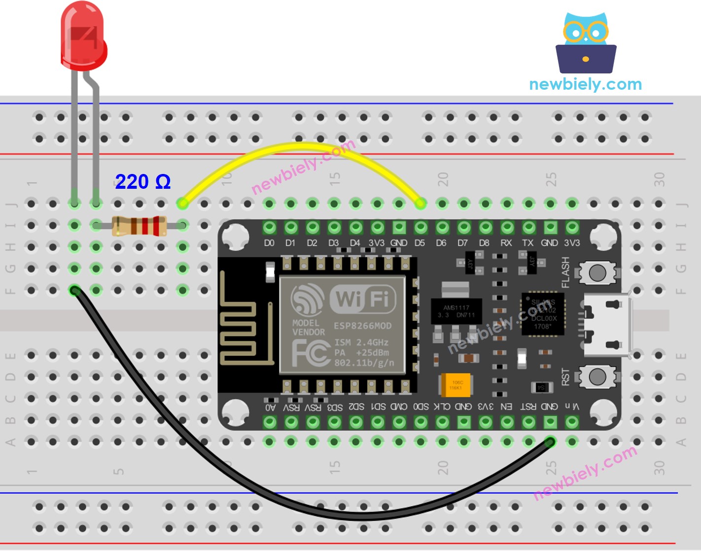
This image is created using Fritzing. Click to enlarge image
See more in ESP8266's pinout and how to supply power to the ESP8266 and other components.
How To Program
- Set the pin of an ESP8266 to digital output mode with the pinMode() function. As an example, this can be done for pin D5:
- Adjust the brightness of the LED by creating a PWM signal with the analogWrite() function.
The brightness can range from 0 to 255.
ESP8266 Code - Fade Example from Arduino IDE
Detailed Instructions
To get started with ESP8266 on Arduino IDE, follow these steps:
- Check out the how to setup environment for ESP8266 on Arduino IDE tutorial if this is your first time using ESP8266.
- Wire the components as shown in the diagram.
- Connect the ESP8266 board to your computer using a USB cable.
- Open Arduino IDE on your computer.
- Choose the correct ESP8266 board, such as (e.g. NodeMCU 1.0 (ESP-12E Module)), and its respective COM port.
- Attach ESP8266 to your computer with a USB cable.
- Open the Arduino IDE, and select the correct board and port.
- Copy the below code and paste it to the Arduino IDE.
- Click the Upload button on Arduino IDE to compile and upload the code to the ESP8266 board.

- Check out the luminosity of the LED.
Code Explanation
Check out the line-by-line explanation contained in the comments of the source code!
※ NOTE THAT:
The example above makes use of the delay() function to fade-in and fade-out. This, however, causes the LED to fade in an unsmooth manner and blocks other code from running. In the upcoming sections, we will learn how to fade-in and fade-out smoothly without interrupting other code by utilizing the millis() function.
How to fade-in LED in a period without using delay()
How to fade-out LED in a period without using delay()
Video Tutorial
Additional Knowledge
- The analogWrite() function in ESP8266 can generate a PWM signal, which causes a LED to fade. However, if a customized function is created with advanced knowledge, it can generate a low-frequency PWM signal, resulting in the LED blinking instead of fading.
- In summary, PWM signals can be used in ESP8266 for a variety of purposes, such as controlling servo motors, DC motors, making sound with a piezo buzzer, fading LEDs, and blinking LEDs.