ESP8266 - Relay
In a prior tutorial, we discovered how to switch on/off an LED using ESP8266. This tutorial instructs you how to activate/deactivate certain devices that make use of a high voltage power source (e.g. a light bulb, fan, electromagnetic lock, linear actuator...) by using ESP8266.
? What are the commons and differences between controlling an LED and controlling a light bulb by using Arduino?
The common: We use the Arduino's output pin to turn on and off, The common: Similar to controlling an LED.
The difference:
- For LED, we can use the power from the ESP8266 board. This allows us to connect LED directly to an ESP8266 pin.
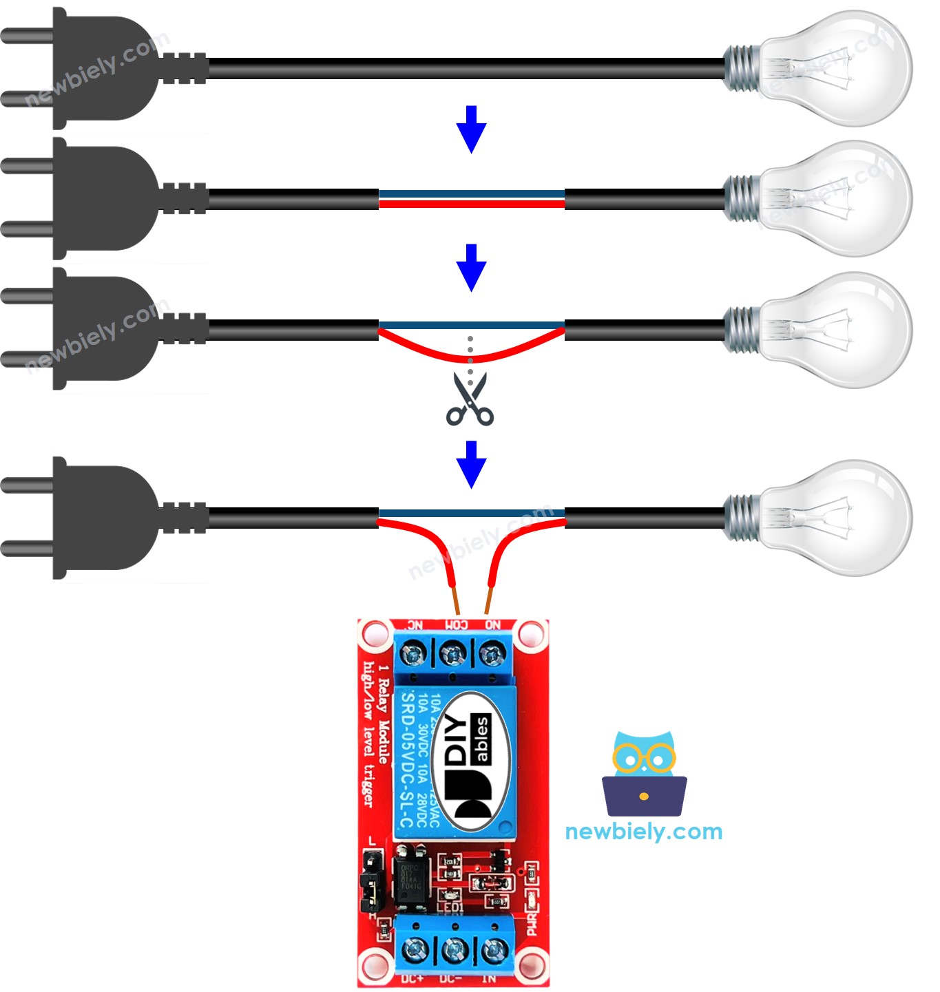
- For the light bulb, we MUST use an additional power source with high voltage and/or high current, which could damage the ESP8266. Therefore, we CANNOT connect the light bulb directly to an ESP8266 pin. We need to use a relay between the ESP8266 pin and the light bulb in order to protect the ESP8266 from the high voltage/current.
Hardware Preparation
Or you can buy the following kits:
| 1 | × | DIYables Sensor Kit (18 sensors/displays) |
Additionally, some of these links are for products from our own brand, DIYables .
Overview of Relay
A relay is an electrical switch that can be programmed by ESP8266 or any micro-controller. It is utilized to control devices that use high voltage and/or high current in a programmatic way.
It acts as a bridge between ESP8266 and high voltage components.
WARNING
When you are creating projects that involve mains voltage, it is important to be aware of the potential danger. We urge you to be careful and not to proceed if you are not completely sure of what you are doing. It is better to ask someone who knows than to risk getting shocked.
Although some relays can be used with both DC and AC devices, we strongly suggest using a DC device with a voltage of 24V or less for testing purposes.
Relay Pinout
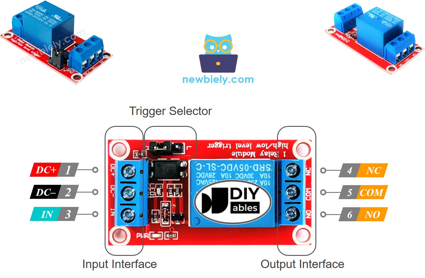
Relay has two sets of pins: one for the input (low voltage) and another for the output (high voltage).
- The input group pins are connected to ESP8266, including three pins:
- DC- pin: must be connected to GND (0V)
- DC+ pin: must be connected to VCC (5V)
- IN pin: receives the control signal from ESP8266
- The output group pins are connected to the high voltage device, including three pins (usually in screw terminal):
- NO pin: is the normally open pin. It is used in the normally open mode
- NC pin: is the normally closed pin. It is used in the normally closed mode
- COM pin: is the common pin. It is used in both normally open and normally closed modes
- If we use the normally open mode, we only need the COM pin and NO pin.
- If we use the normally closed mode, we only need the COM pin and NC pin.
- Triggering at a LOW level, called LOW level trigger mode.
- Triggering at a HIGH level, called HIGH level trigger mode.
- normally open mode
- normally closed mode. These modes are opposite to each other.
- The normally open and normally closed modes operate inversely
- Most relay modules support both normally open and normally closed modes
- The LOW level trigger and HIGH level trigger modes work inversely
- Not all relay modules support both LOW level trigger and HIGH level trigger modes
- At any given time, the relay module can only be in one of the two LOW level trigger and HIGH level trigger modes
- Linking an Arduino's pin to the IN pin of the relay
- Programming the pin to LOW or HIGH to control the relay
Generally, we do not utilize all of the pins in the high voltage group. We just use two of them:
In addition, if the relay has both LOW and HIGH level triggers, there is usually a jumper to choose between them.
※ NOTE THAT:
The arrangement of the pins on a relay module can differ among manufacturers. It is crucial to always refer to the labels printed on the relay module when working with it. Pay close attention.
How to Connect the High Voltage Device to Relay
How It Works
The way a relay functions may vary depending on the manufacturer and how it is installed by the user.
For the IN pin, there are two input modes that make the relay operate in opposite ways:
The output mode (for output pins): There are two modes that make the relay work in a different way:
The term "normally" implies "if the IN pin is linked to LOW (0V)".
Before delving into the details, here is some quick information:
The combination of input modes and output modes generates a range of applications. If you are just starting out, we suggest using HIGH level trigger mode and normally open mode.
The HIGH level trigger mode will be explained in detail. As the LOW level trigger works in an opposite manner, this will be discussed separately.
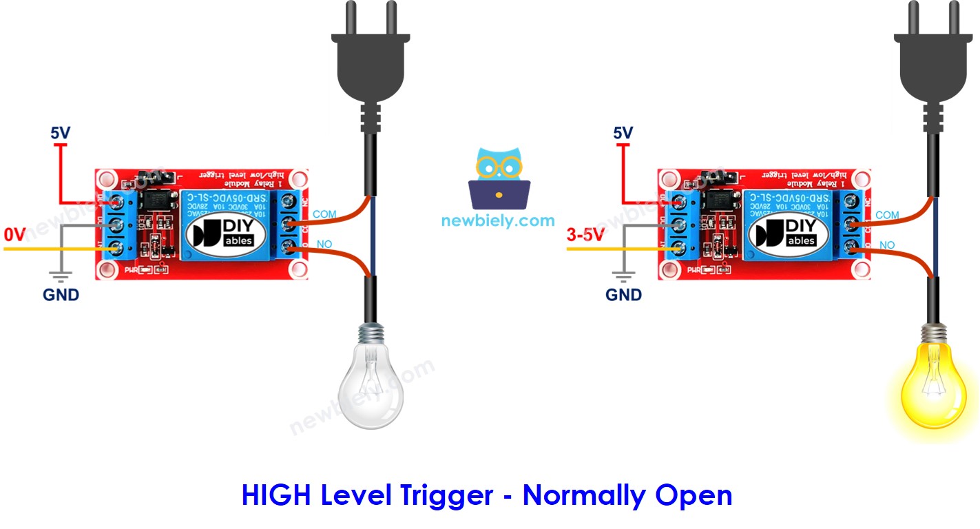
HIGH Level Trigger - Normally Open Mode
In order to employ this mode, it is necessary to attach the high voltage device to the COM and NO pins.
When the IN pin is linked to LOW (0V), the switch is open and the device is OFF (or inactive).
Conversely, when the IN pin is linked to HIGH (5V), the switch is closed and the device is ON (or active).
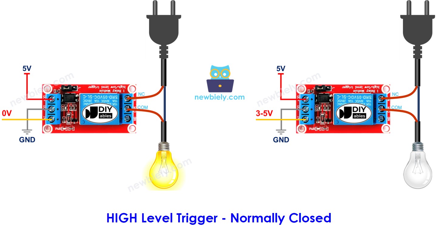
HIGH Level Trigger - Normally Closed Mode
In order to utilize this mode, the high voltage device must be connected to the COM pin and NC pin.
When the IN pin is linked to LOW (0V), the switch is shut. This means the device is ON (or active).
Conversely, if the IN pin is linked to HIGH (5V), the switch is open. This implies the device is OFF (or inactive).
Summary
| Input modes | Output Modes | IN pin (programmable) | Output pins | Relay state | Device state |
|---|---|---|---|---|---|
| HIGH Trigger | Normally Open | LOW | COM and NO pin | ⇒ open | ⇒ OFF |
| HIGH Trigger | Normally Open | HIGH | COM and NO pin | ⇒ closed | ⇒ ON |
| HIGH Trigger | Normally Closed | LOW | COM and NC pin | ⇒ closed | ⇒ ON |
| HIGH Trigger | Normally Closed | HIGH | COM and NC pin | ⇒ open | ⇒ OFF |
| LOW Trigger | Normally Open | LOW | COM and NO pin | ⇒ closed | ⇒ ON |
| LOW Trigger | Normally Open | HIGH | COM and NO pin | ⇒ open | ⇒ OFF |
| LOW Trigger | Normally Closed | LOW | COM and NC pin | ⇒ open | ⇒ OFF |
| LOW Trigger | Normally Closed | HIGH | COM and NC pin | ⇒ closed | ⇒ ON |
There are a maximum of 8 use cases. It may be overwhelming. However, if you are a beginner, you only need to pay attention to the first two cases, which involve HIGH level trigger and normally open. The remainder of this tutorial will focus on those two use cases.
ESP8266 - Relay
ESP8266 manages a relay, which in turn, controls a high voltage device.
Managing a relay is straightforward. All that is required is:
Wiring Diagram
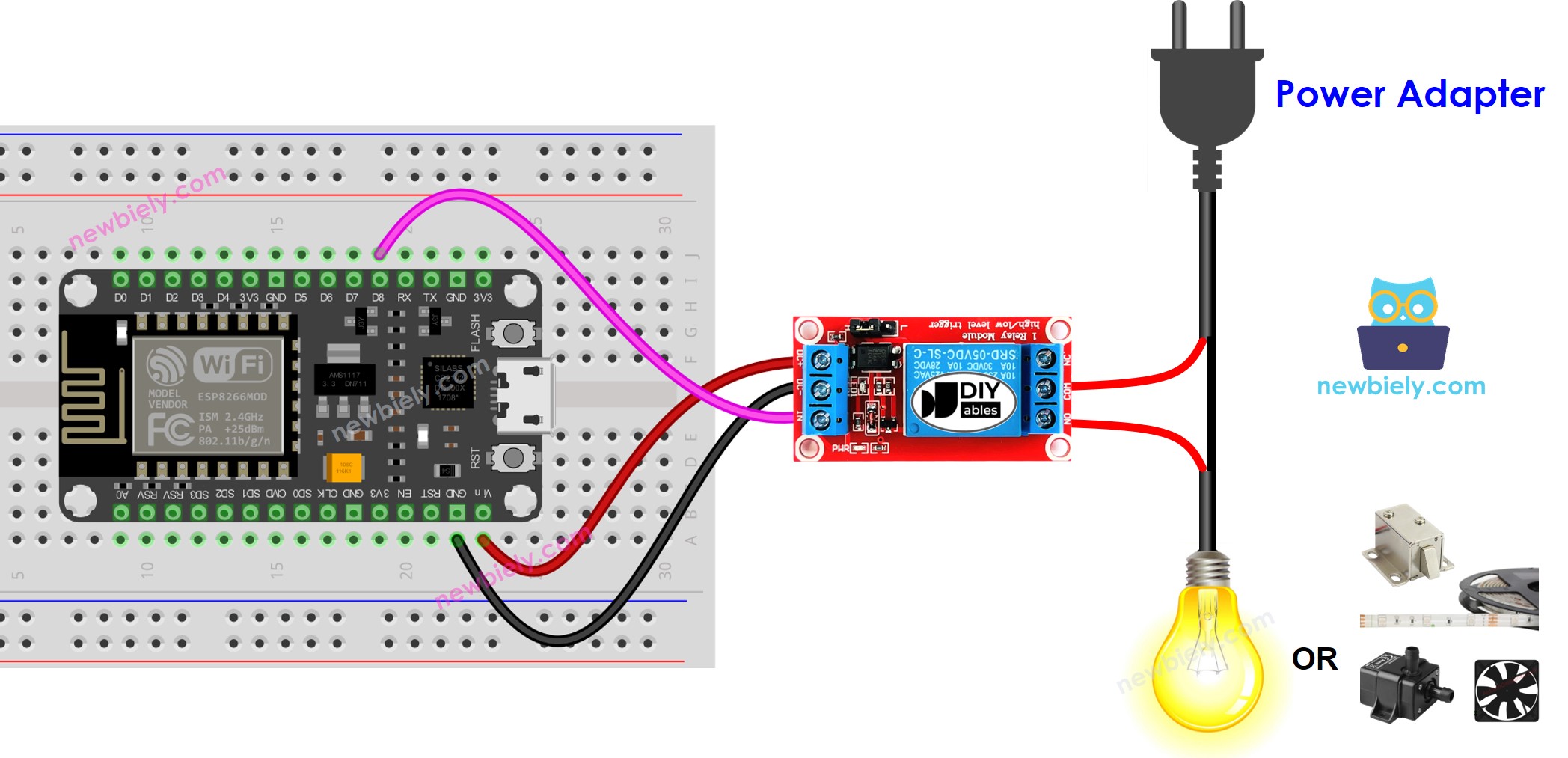
This image is created using Fritzing. Click to enlarge image
See more in ESP8266's pinout and how to supply power to the ESP8266 and other components.
How To Program For Relay
- Set an Arduino's pin to digital output mode by utilizing the pinMode() function. As an example, pin 3:
- Set the pin to 0V by utilizing the digitalWrite() function:
- Set the pin to 5V by utilizing the digitalWrite() function:
ESP8266 Code
Detailed Instructions
To get started with ESP8266 on Arduino IDE, follow these steps:
- Check out the how to setup environment for ESP8266 on Arduino IDE tutorial if this is your first time using ESP8266.
- Wire the components as shown in the diagram.
- Connect the ESP8266 board to your computer using a USB cable.
- Open Arduino IDE on your computer.
- Choose the correct ESP8266 board, such as (e.g. NodeMCU 1.0 (ESP-12E Module)), and its respective COM port.
- Copy the code above and open it in the Arduino IDE.
- Click the Upload button in the Arduino IDE to send the code to the ESP8266.
- Check out the LED strip, which should be blinking.
Video Tutorial
Challenge Yourself
- When you enter your room, the light will be automatically switched on. After you leave, it will turn off after 30 seconds. Refer to ESP8266 - Motion Sensor for more information.