ESP8266 - 28BYJ-48 Stepper Motor ULN2003 Driver
This tutorial instructs you how to use ESP8266 to control 28BYJ-48 Stepper Motor using ULN2003 Driver. In detail, we will learn:
- How to connect ESP8266 to 28BYJ-48 stepper motor via ULN2003 driver
- How to program ESP8266 to control a 28BYJ-48 stepper motor via ULN2003 driver
Hardware Preparation
Or you can buy the following kits:
| 1 | × | DIYables Sensor Kit (18 sensors/displays) |
Additionally, some of these links are for products from our own brand, DIYables .
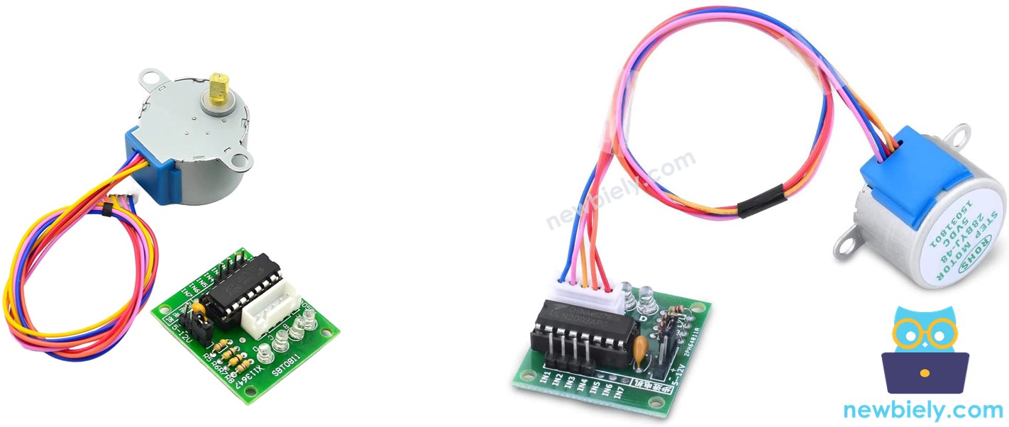
Overview of 28BYJ-48 Stepper Motor
Stepper motors are ideal for position control. They break down a full revolution into a set of equal "steps". These motors are used in a variety of devices, including printers, 3D printers, CNC machines, and industrial automation.
One of the cost-effective methods to gain knowledge about stepper motors is to utilize 28BYJ-48 stepper motors. These usually come with a ULN2003 based driver board, making them effortless to use.
As indicated in the data sheet, the 28BYJ-48 motor operates in full-step mode, with each step representing an 11.25° rotation. Therefore, there are 32 steps in a single revolution (360°/11.25° = 32).
Furthermore, the motor has a 1/64 reduction gear set. This translates to 32 x 64 = 2048 steps. Each step is equivalent to 360°/2048 = 0.1758°.
Conclusion: If the motor is set to full-step mode, it will take 2048 steps for it to complete one revolution.
The 28BYJ-48 Stepper Motor using ULN2003 Driver Pinout
The 28BYJ-48 stepper motor has 5 pins. We do not need to be concerned with the specifics of these pins. All we need to do is plug it into the ULN2003 motor driver connector.
Overview of ULN2003 Stepper Motor Driver Module
The ULN2003 is a widely used motor driver module for stepper motors.
- It has four LEDs that display the activity of four control input lines, which gives an impressive effect when the motor is in motion.
- Additionally, it includes an ON/OFF jumper to separate the power supply to the stepper motor.
ULN2003 Pinout
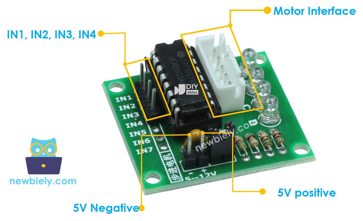
The ULN2003 module has 6 pins and a female connector:
- IN1: This pin is used to drive the motor and should be connected to an output pin on the ESP8266.
- IN2: This pin is used to drive the motor and should be connected to an output pin on the ESP8266.
- IN3: This pin is used to drive the motor and should be connected to an output pin on the ESP8266.
- IN4: This pin is used to drive the motor and should be connected to an output pin on the ESP8266.
- GND: This is a common ground pin and must be connected to both the GNDs of the ESP8266 and the external power supply.
- VDD: This pin supplies power for the motor and should be connected to the external power supply.
- Motor Connector: This is where the motor is plugged in.
※ NOTE THAT:
- The voltage of the external power supply must match the voltage of the stepper motor. For instance, if a stepper motor operates on 12V DC, a 12V power supply should be used. In the case of a 28BYJ-48 stepper motor, which works with 5V DC, a 5V power supply should be used.
- However, even if the stepper motor needs a 5V power supply, the VDD pin should NOT be connected to the 5V pin on the ESP8266. Instead, it should be connected to an external 5V power supply, as the stepper motor draws too much power.
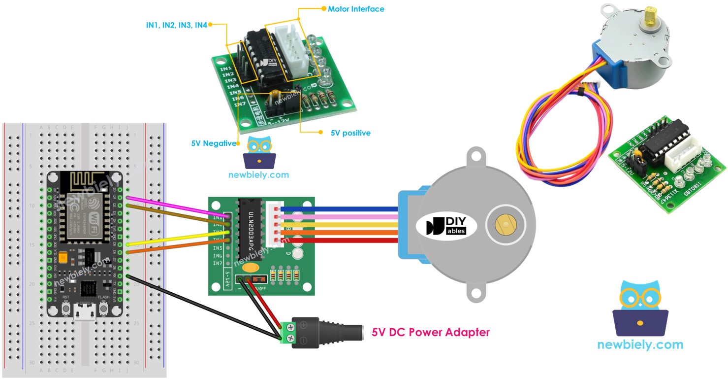
Wiring Diagram
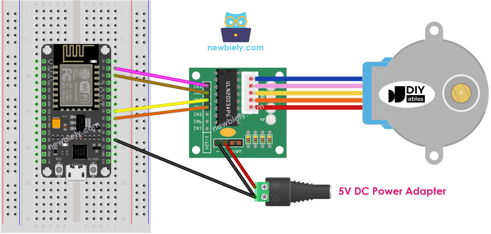
This image is created using Fritzing. Click to enlarge image
See more in ESP8266's pinout and how to supply power to the ESP8266 and other components.
It is not necessary to take into account the colour of the wires of the stepper motor. We just need to plug the male connector of the 28BYJ-48 stepper motor into the female connector of the ULN2003 driver.
How To Program to control a stepper motor
There are three ways of controlling a stepper motor:
- Full-step
- Half-step
- Micro-step
For basic applications, we can use the full-step method. The specifics of the three methods will be discussed in the latter part of this tutorial. Programming these methods can be complex. Fortunately, there are many libraries that have done the work for us, so all we need to do is utilize the library.
The Arduino IDE includes a Stepper library. However, we do not suggest utilizing this library due to the following reasons:
- The library is blocking, meaning it prevents the ESP8266 from performing other tasks while controlling the stepper motor.
- It does not offer enough functions.
Instead, we suggest that you use the AccelStepper library. This library provides:
- Acceleration
- Deceleration
- Full-step and half-step driving
- The ability to control multiple steppers independently
- Disadvantage: Does not support micro-step driving.
ESP8266 Code
Detailed Instructions
To get started with ESP8266 on Arduino IDE, follow these steps:
- Check out the how to setup environment for ESP8266 on Arduino IDE tutorial if this is your first time using ESP8266.
- Wire the components as shown in the diagram.
- Connect the ESP8266 board to your computer using a USB cable.
- Open Arduino IDE on your computer.
- Choose the correct ESP8266 board, such as (e.g. NodeMCU 1.0 (ESP-12E Module)), and its respective COM port.
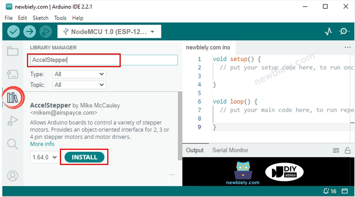
- Click to the Libraries icon on the left bar of the Arduino IDE.
- Search for “AccelStepper” and locate the AccelStepper library created by Mike McCauley.
- Then, press the Install button to install the AccelStepper library.
- Copy the code and open it with the Arduino IDE.
- Click the Upload button to upload the code to the ESP8266.
- Check out the motor rotating.
- It should rotate one revolution in a clockwise direction, followed by two revolutions in an anti-clockwise direction, and then two revolutions in a clockwise direction.
The procedure is done continually.
- Monitor the outcome in the Serial Monitor.
Additional Knowledge
1. Stepper motor vibrates while moving
Do NOT be concerned if the stepper motor shakes while in motion. This is a typical characteristic of the stepper motor. We can reduce the vibration by utilizing the micro-stepping control technique.
Additionally, due to this characteristic, if managed accurately, the stepper motor can generate musical tones as if it were a musical instrument. An example of this can be found here on Hackster.io.
2. Method of controlling stepper motors
- Full-step: The unit of movement is one step, which is equal to the value of degree specified in the stepper motor's datasheet or manual.
- Half-step: Each full step is divided into two smaller steps. The unit of movement is half of the full step. This method allows the motor to move with double resolution.
- Micro-step: Each full step is divided into many smaller steps. The unit of movement is a fraction of the full step. The fraction can be 1/4, 1/8, 1/16, 1/32 or even more. This method allows the motor to move with higher resolution. It also makes the motor move smoother at low speeds. The bigger the dividend is, the higher the resolution and the smoother the motion will be.
If the motor's datasheet specifies 1.8 degree/step:
- Full-step: The motor can move in increments of 1.8 degrees per step, resulting in 200 steps per revolution.
- Half-step: The motor can move in increments of 0.9 degrees per step, resulting in 400 steps per revolution.
- Micro-step: The motor can move in increments of 0.45, 0.225, 1125, 0.05625 degrees per step, resulting in 800, 1600, 3200, 6400... steps per revolution.
The code above used the full-step control technique.
3. Resonance Issue
This is for advanced users. Beginners do not need to take note of it. It occurs in a range of speeds, where the step rate is equal to the motor's natural frequency. There could be a noticeable change in the noise made by the motor, as well as an increase in vibration. In actual applications, developers should be aware of this.