ESP8266 - 4-Channel Relay Module
When we need to control four high-voltage devices such as pumps, fans, and actuators, we can use multiple relay modules. Yet, there is a more straightforward option: a 4-channel relay module. This is a board that contains four relays combined together.
A 4-channel relay module compared to 4 x 1-channel relay modules:
- The wiring is simpler with the 4-channel relay module.
- The 4-channel relay module requires less space.
- The 4-channel relay module is more cost-effective.
- The programming remains the same.
Hardware Preparation
Or you can buy the following kits:
| 1 | × | DIYables Sensor Kit (18 sensors/displays) |
Additionally, some of these links are for products from our own brand, DIYables .
Overview of 4-Channel Relay Module
The 4-Channel Relay Module Pinout
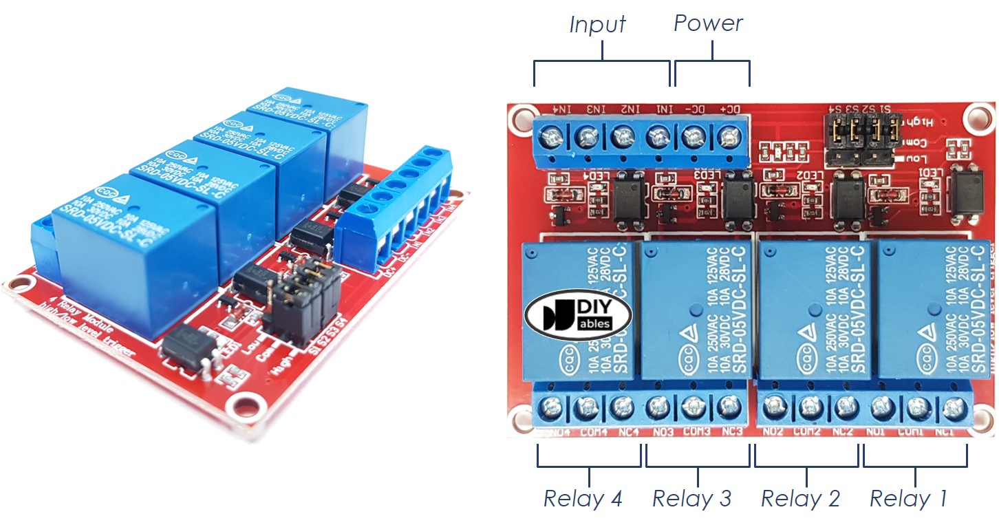
A 4-channel relay module has the following pins:
- Power pins for relay boards
- DC+: connect this pin to the 5V pin of a power supply
- DC-: connect this pin to the GND pin of the power supply and also to the GND pin of an ESP8266
- Signal pins:
- IN1: this pin receives the control signal from an ESP8266 to control relay 1 on the module
- IN2: this pin receives the control signal from an ESP8266 to control relay 2 on the module
- IN3: this pin receives the control signal from an ESP8266 to control relay 3 on the module
- IN4: this pin receives the control signal from an ESP8266 to control relay 4 on the module
- Output pins: NCx (normally closed pin), NOx (normally open pin), COMx (common pin),
- NC1, NO1, COM1: These pins connect to a high-voltage device that is controlled by relay 1
- NC2, NO2, COM2: These pins connect to a high-voltage device that is controlled by relay 2
- NC3, NO3, COM3: These pins connect to a high-voltage device that is controlled by relay 3
- NC4, NO4, COM4: These pins connect to a high-voltage device that is controlled by relay 4
For information on how to connect a relay to high-voltage, and the differences between normally closed and normally open, please refer to ESP8266 - Relay tutorial
It also has 4 jumpers, which can be used to choose between the low trigger and the high trigger for each relay respectively.
Wiring Diagram
The 4-channel relay module requires a considerable amount of power, thus it should NOT be powered directly from the 5V pin of the ESP8266. An external 5V power source should be used for the module instead.
Therefore, we must use three power sources:
- A 5V power adapter for the ESP8266
- A 5V power adapter for the 4-channel relay module
- A higher-voltage power adapter (12VDC, 24VDC, 48VDC, 220AC...) for the items that are managed by the 4-channel relay module
- A wiring diagram with the three power sources. The power supply for the ESP8266 (not included in the image) can be either via USB cable or power jack.
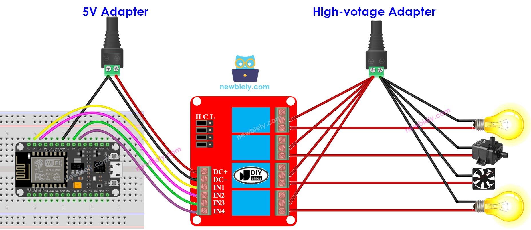
This image is created using Fritzing. Click to enlarge image
See more in ESP8266's pinout and how to supply power to the ESP8266 and other components.
- We can decrease the amount of power adapters by utilizing one 5V power source for both the ESP8266 and the 4-channel relay module.
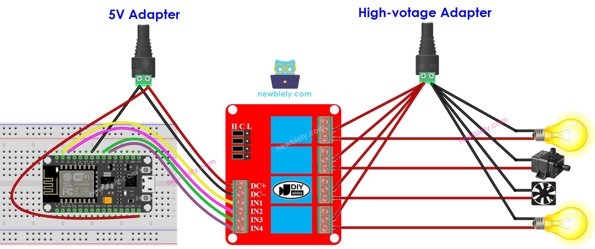
This image is created using Fritzing. Click to enlarge image
※ NOTE THAT:
If the four devices that are managed by a 4-channel relay module have the same voltage, then one high-voltage power adapter can be used for all of them. However, if the voltage is different for each device, then separate high-voltage power adapters must be used.
How To Program For 4-Channel Relay Module
- Sets the ESP8266 pin to digital output mode with the pinMode() function.
- Manipulate the relay's state with the digitalWrite() function.
ESP8266 Code
Detailed Instructions
To get started with ESP8266 on Arduino IDE, follow these steps:
- Check out the how to setup environment for ESP8266 on Arduino IDE tutorial if this is your first time using ESP8266.
- Wire the components as shown in the diagram.
- Connect the ESP8266 board to your computer using a USB cable.
- Open Arduino IDE on your computer.
- Choose the correct ESP8266 board, such as (e.g. NodeMCU 1.0 (ESP-12E Module)), and its respective COM port.
- Copy the code and open it with the Arduino IDE.
- Click the Upload button in the IDE to send the code to the ESP8266.
- Listen for the click sound of the relays.
- Check the Serial Monitor to observe the result.