ESP8266 - Keypad
This tutorial instructs you how to use ESP8266 with keypad 3x4 and 4x4. In detail, we will learn:
- How to connect ESP8266 to keypad 3x4 and keypad 4x4.
- How to program ESP8266 to read value from keypad 3x4 and keypad 4x4.
- How ESP8266 checks the password inputted from keypad 3x4 and keypad 4x4.
Hardware Preparation
Or you can buy the following kits:
| 1 | × | DIYables Sensor Kit (18 sensors/displays) |
Additionally, some of these links are for products from our own brand, DIYables .
Overview of Keypad
A keypad is a collection of keys that are organized in rows and columns, referred to as a matrix. Each button is known as a key. Keypads come in a variety of styles. Two of the most common for DIY projects are the 3x4 keypad (with 12 keys) and the 4x4 keypad (with 16 keys).
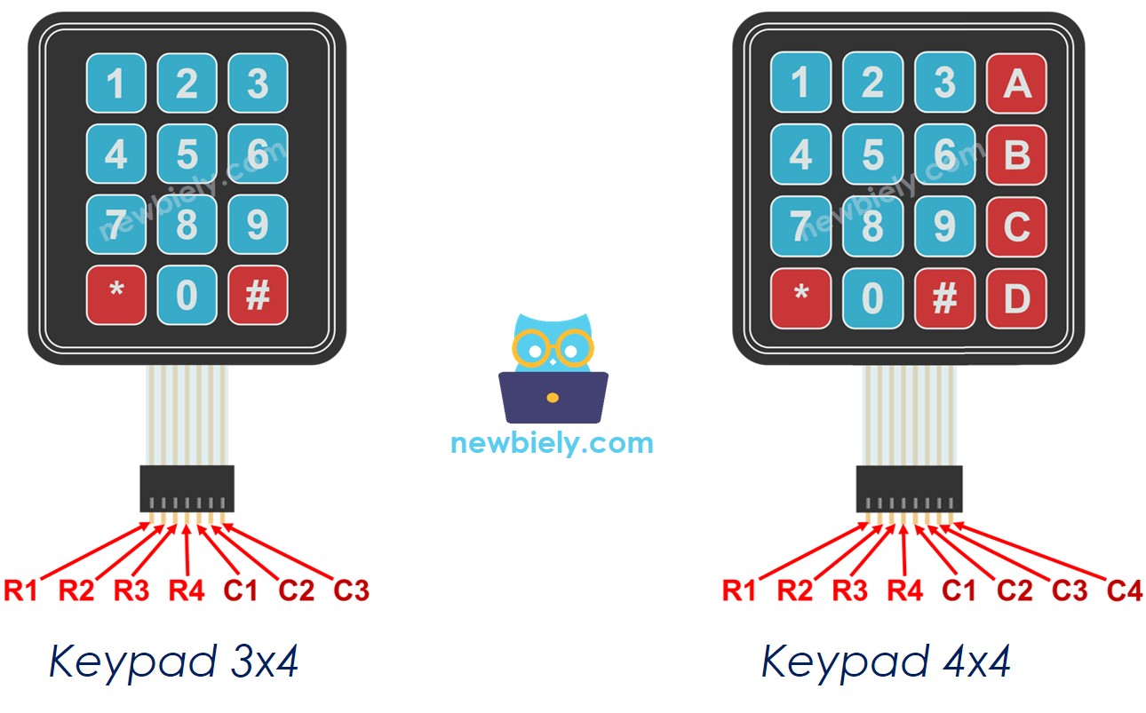
The Keypad Pinout
The pins are categorized into two groups: rows and columns.
- A 3x4 keypad has 7 pins: Four pins for the rows (labeled R1, R2, R3 and R4), and four pins for the columns (labeled C1, C2 and C3).
- A 4x4 keypad has 8 pins: Four pins for the rows (labeled R1, R2, R3 and R4), and four pins for the columns (labeled C1, C2, C3 and C4).
Wiring Diagram
- ESP8266 - Keypad 3x4 wiring diagram
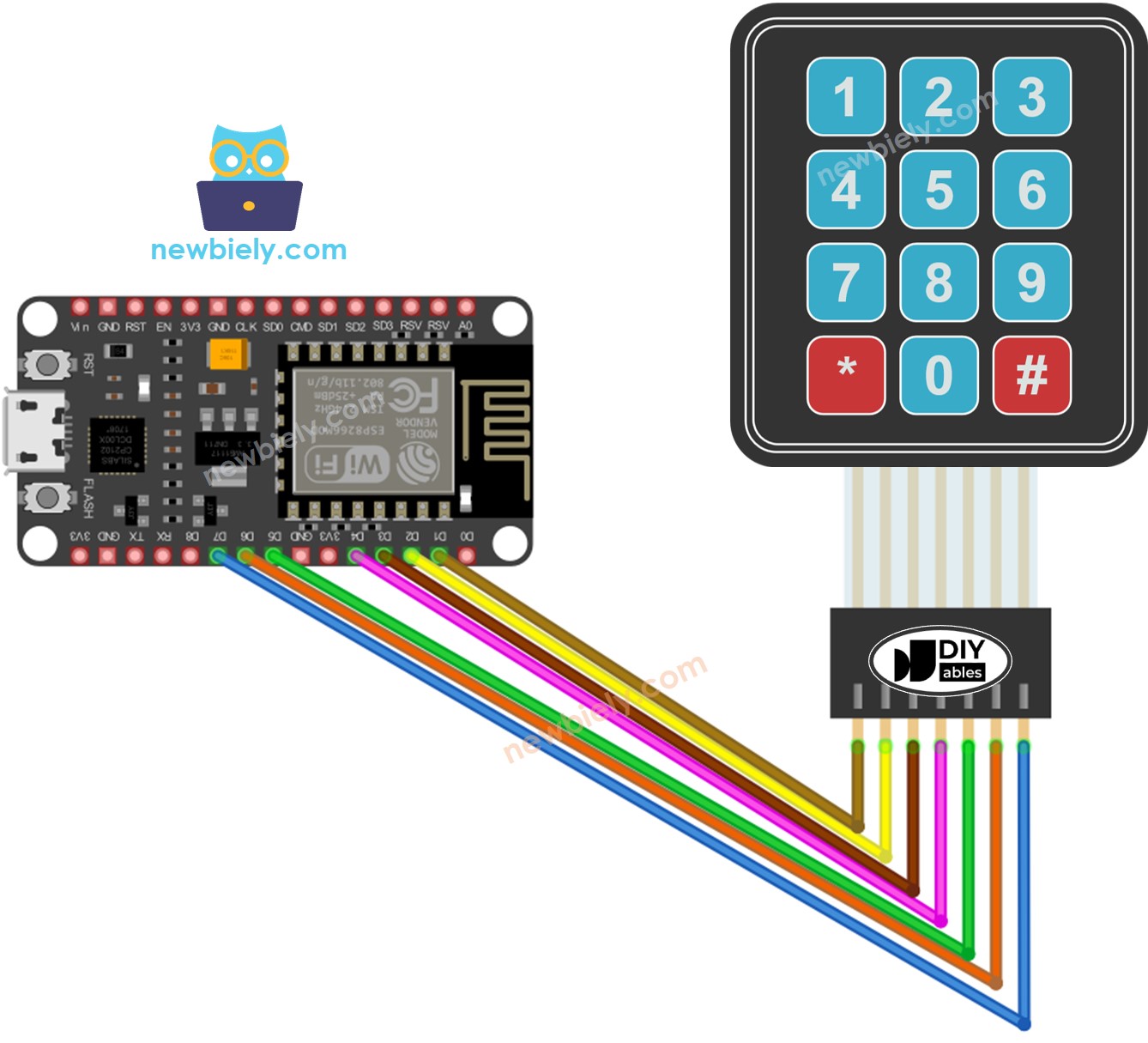
This image is created using Fritzing. Click to enlarge image
- ESP8266 - Keypad 4x4 wiring diagram
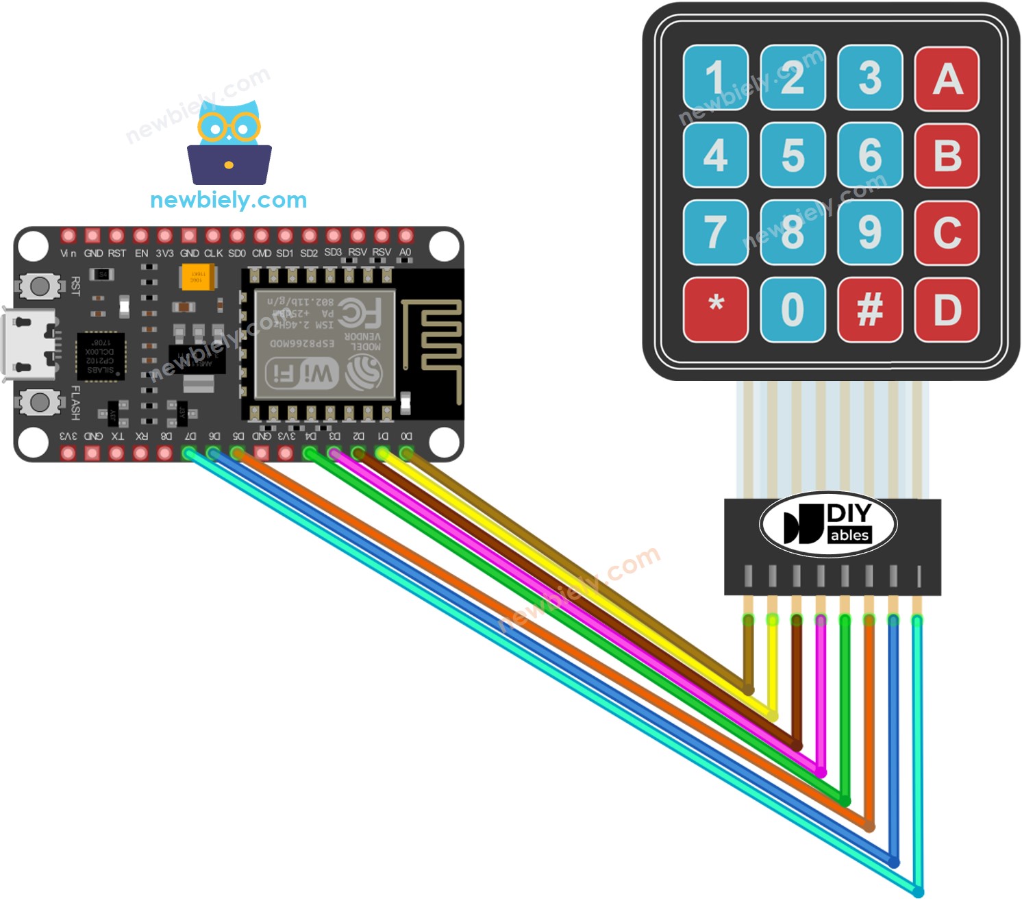
This image is created using Fritzing. Click to enlarge image
See more in ESP8266's pinout and how to supply power to the ESP8266 and other components.
※ NOTE THAT:
You can change the ESP8266 pins connected to the keypad pins. However, you should avoid using pin D8 for the keypad. If, however, the ESP8266 pins are not enough, you can use pin D8 for the keypad but MUST follow the instructions below:
- Do NOT use the ESP8266 pin D8 for row pins.
- When using the ESP8266 pin D8 for a column pin, you MUST modify the Keypad library as follows:
- Find the Arduino\libraries\Keypad\src\Keypad.cpp file, go to line 98, where it looks like this: pin_mode(columnPins[c], INPUT);
- Comment out this line. After modification, the code at line 98 should look like this: //pin_mode(columnPins[c], INPUT);
ESP8266 Code
ESP8266 Code for Keypad 3x4
ESP8266 Code for Keypad 4x4
Detailed Instructions
To get started with ESP8266 on Arduino IDE, follow these steps:
- Check out the how to setup environment for ESP8266 on Arduino IDE tutorial if this is your first time using ESP8266.
- Wire the components as shown in the diagram.
- Connect the ESP8266 board to your computer using a USB cable.
- Open Arduino IDE on your computer.
- Choose the correct ESP8266 board, such as (e.g. NodeMCU 1.0 (ESP-12E Module)), and its respective COM port.
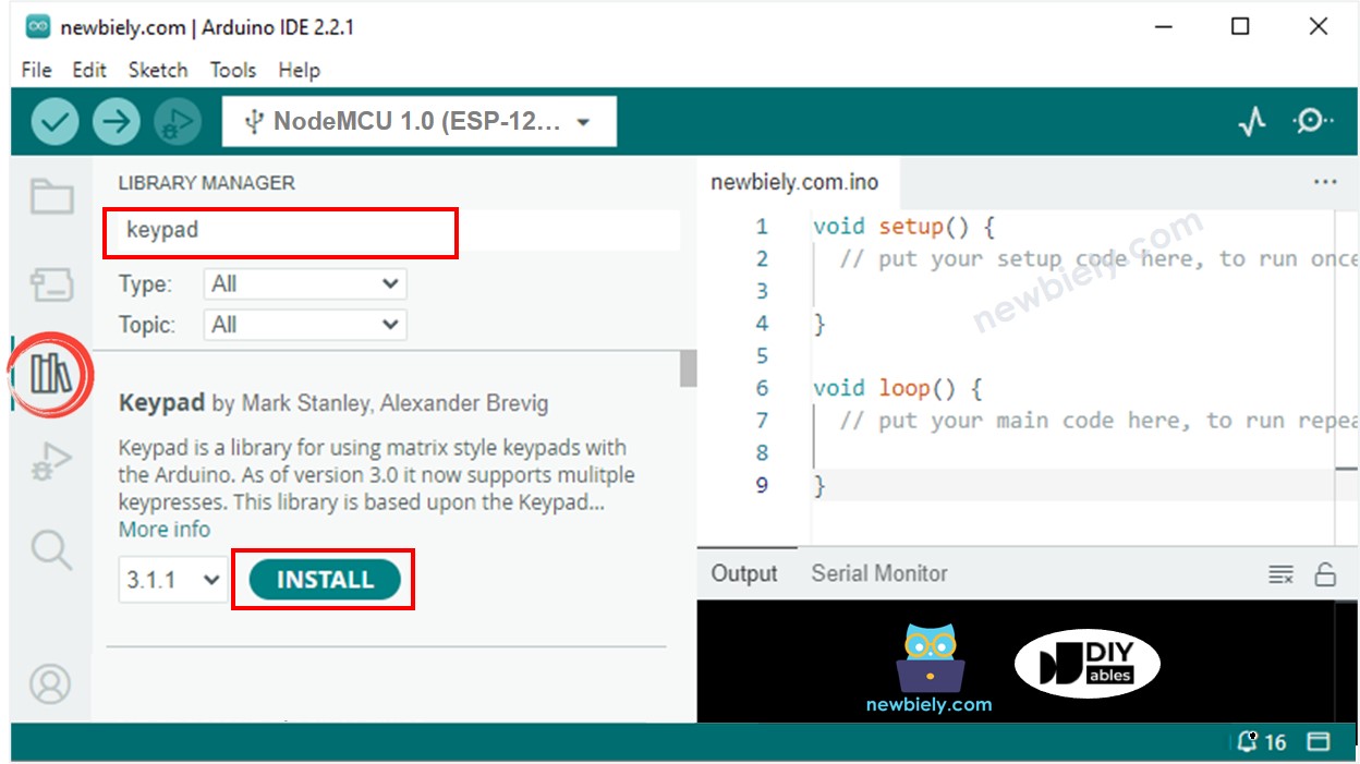
- Click to the Libraries icon on the left bar of the Arduino IDE.
- Search for “keypad” and locate the keypad library created by Mark Stanley and Alexander Brevig.
- Then, click the Install button to complete the installation of the keypad library.
- Copy the code above and open it in the Arduino IDE.
- Once opened, click the Upload button to upload the code to the ESP8266.
- Open the Serial Monitor.
- Press some keys on the keypad.
- Check the Serial Monitor to see the result.
Keypad and Password
A common use of a keypad is for entering passwords. We typically designate two specific keys for this purpose:
- A key to initiate or restart the password entry. For instance, the "*" key.
- A key to end the password entry. For instance, the "#" key.
The password will comprise of a string which includes all the other keys, apart from two specific special keys.
When a key is pressed:
- If the key is not "*" or "#", add the key to the user's input password string.
- If the key is "#", compare the user's input string with the predefined passwords to decide if the input password is correct, and then erase the user's input password string.
- If the key is "*", erase the user's input password string.
Keypad - Password Code
Detailed Instructions
- Run the code above.
- Open the Serial Monitor.
- Press the keys "123456" and then press "#".
- Afterwards, press the keys "1234" and then press "#".
- Check out the result on the Serial Monitor.