ESP8266 - Sound Sensor
The sound sensor has the capability to detect the presence of sound in its surroundings. It can be employed to create projects that respond to sound, like lights that activate with a clap or a pet feeder that responds to sound cues.
This tutorial instructs you how to use the ESP8266 and a sound sensor to detect sound. We will explore:
- How to connect the sound sensor to the ESP8266
- How to program the ESP8266 to detect sound using the sound sensor.
Subsequently, you have the option to modify the code to trigger the activation of an LED or a light (using a relay) upon sound detection, or even make a servo motor rotate.
Hardware Preparation
Or you can buy the following kits:
| 1 | × | DIYables Sensor Kit (18 sensors/displays) |
Additionally, some of these links are for products from our own brand, DIYables .
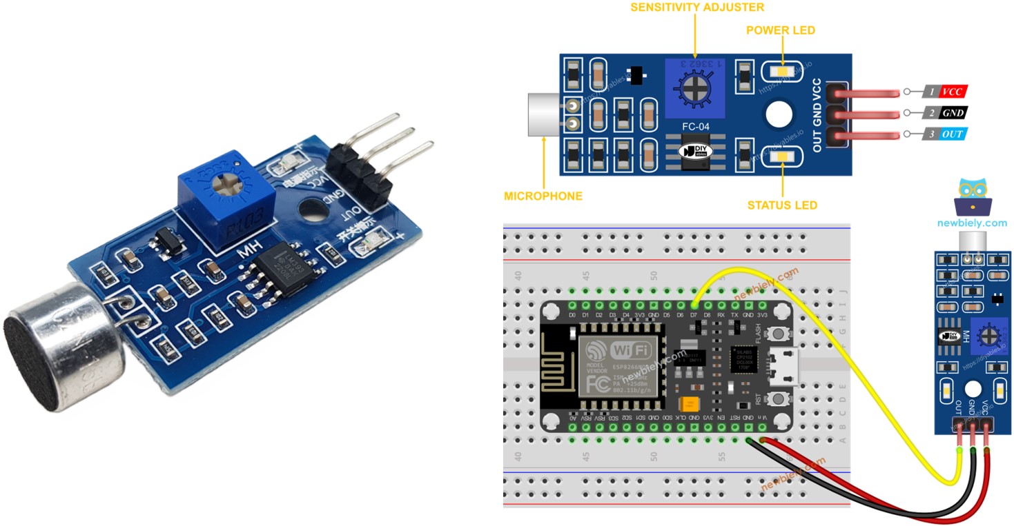
Overview of Sound Sensor
The sound sensor can be used to detect sound in the environment around it. There are two types of sound sensor module:
- Digital sound sensor module: outputs the digital signal value (ON/OFF)
- Analog sound sensor module: outputs both analog and digital signal value
The sensitivity of digital output can be addjusted by using a built-in potentiometer.
The Digital Sound Sensor Pinout
The sound sensor includes three pins:
- VCC pin: needs to be connected to VCC (3.3V to 5V)
- GND pin: needs to be connected to GND (0V)
- OUT pin: is an output pin: HIGH if quiet and LOW if sound is detected. This pin needs to be connected to ESP8266's input pin.
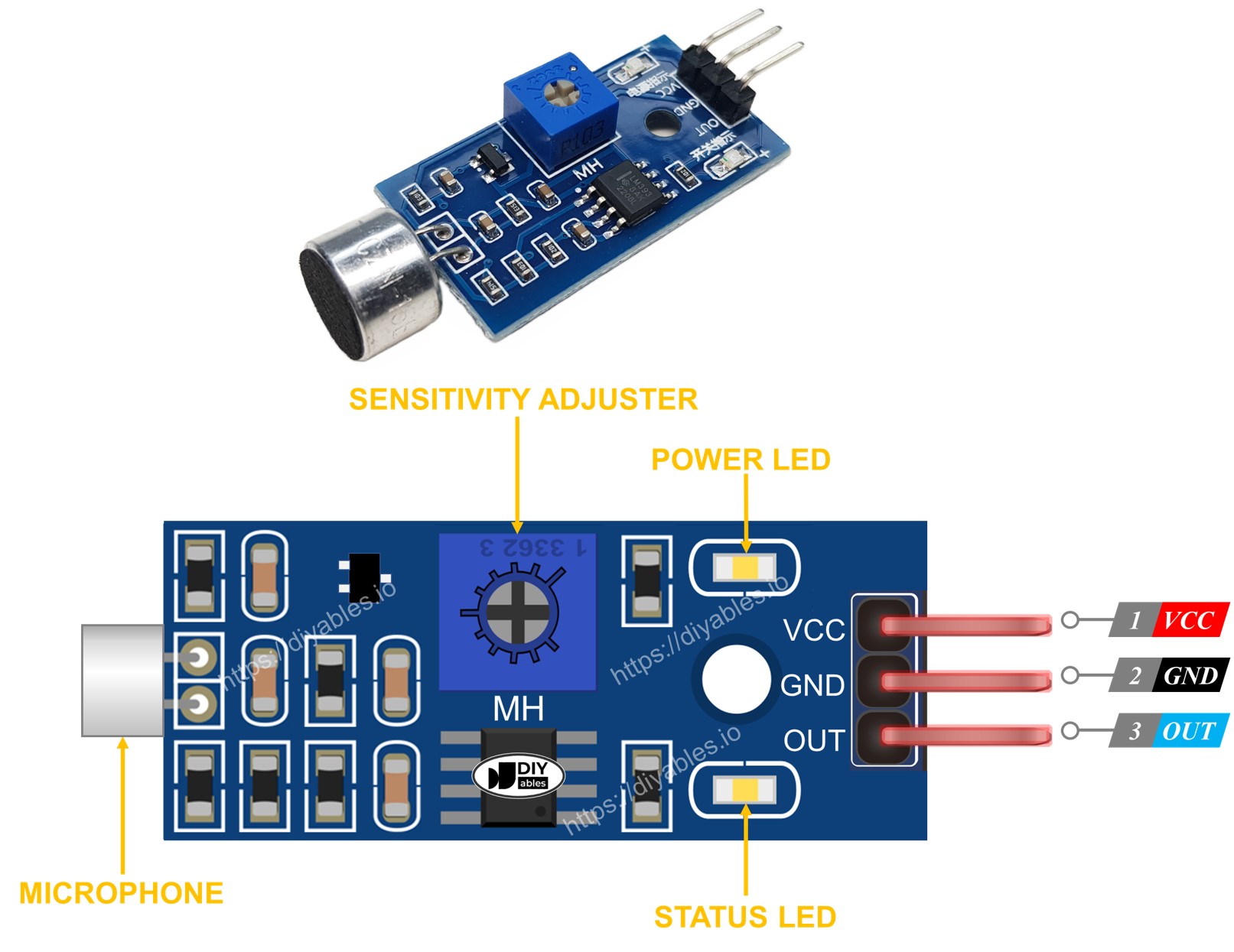
The sound sensor comes with a handy potentiometer that allows you to easily adjust its sensitivity. Additionally, it features two LED indicators:
- One LED indicates the power status
- Another LED indicates the sound state: it turns on when sound is detected and off when it's quiet.
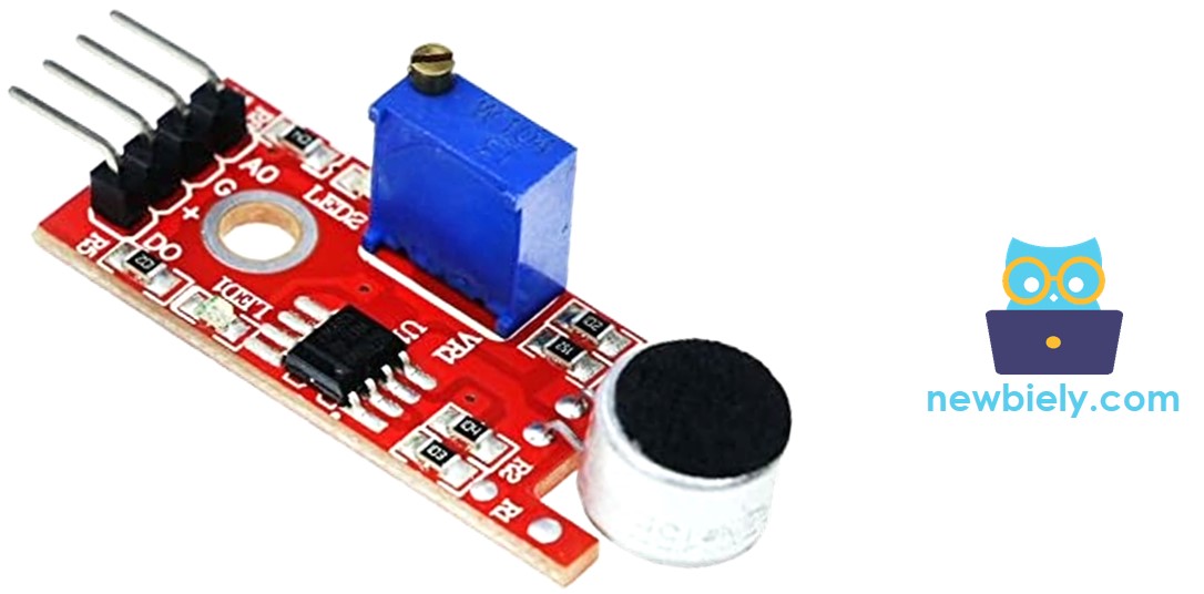
The Analog Sound Sensor Pinout
The analog sound sensor includes four pins:
- + pin: needs to be connected to 5V
- G pin: needs to be connected to GND (0V)
- DO pin: is a digital output pin: HIGH if quiet and LOW if sound is detected. This pin needs to be connected to ESP8266's digital input pin.
- AO pin: is an analog output pin: outputs the analog value indicated sound level. This pin needs to be connected to ESP8266's analog input pin.
How It Works
The module includes a convenient built-in potentiometer that allows you to adjust the sound sensitivity. Here's how the sensor behaves:
- When sound is detected, the output pin of the sensor is set to LOW.
- When sound is not detected, the output pin of the sensor is set to HIGH.
Wiring Diagram
- The wiring diagram between ESP8266 and sound sensor when powering via USB port
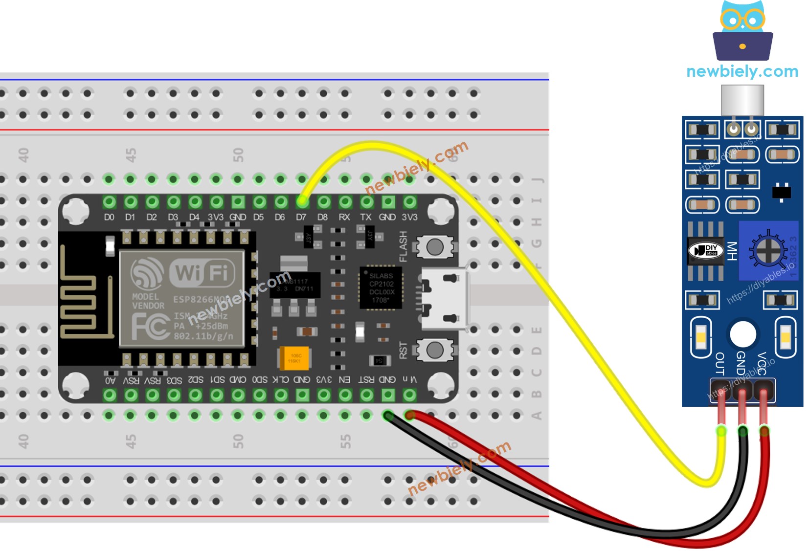
This image is created using Fritzing. Click to enlarge image
- The wiring diagram between ESP8266 and sound sensor when powering via Vin
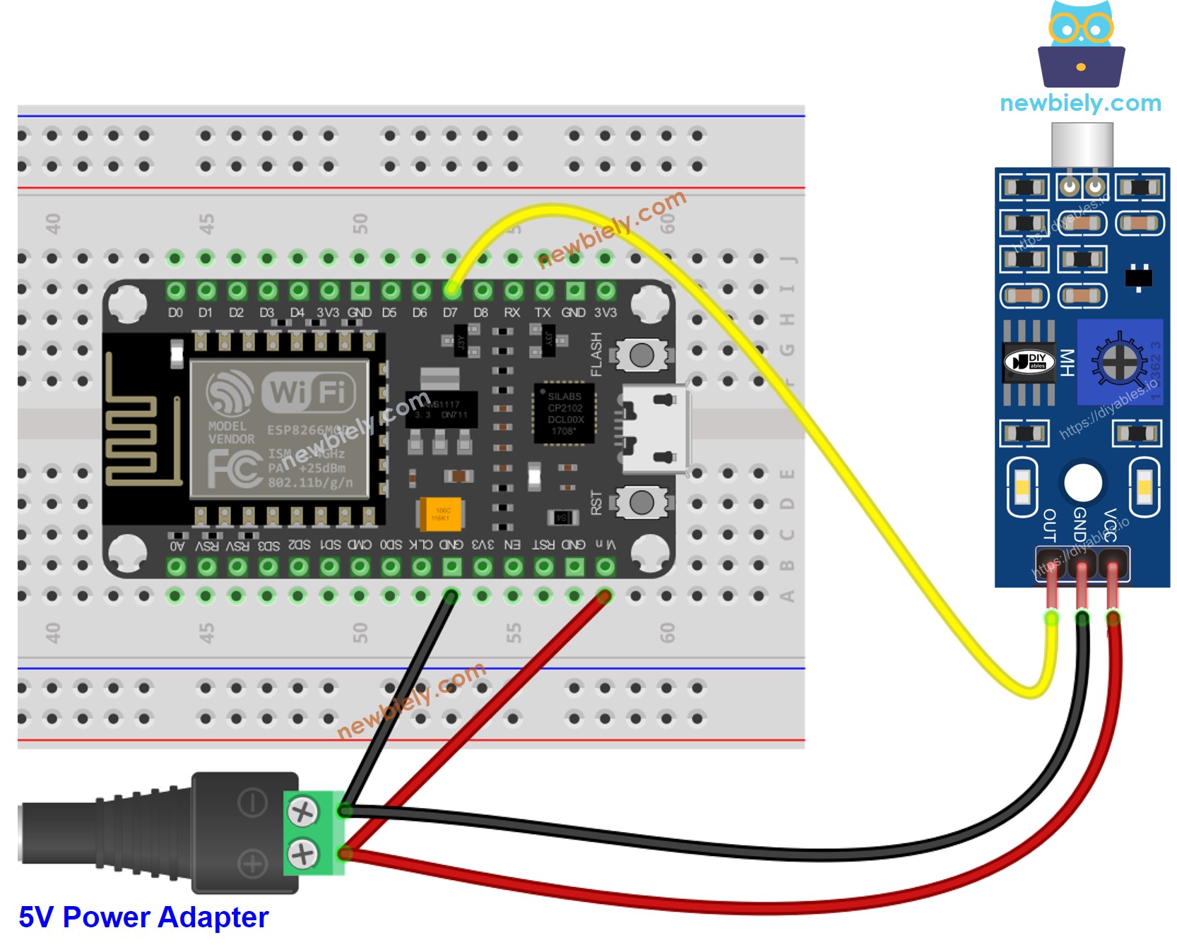
This image is created using Fritzing. Click to enlarge image
See more in ESP8266's pinout and how to supply power to the ESP8266 and other components.
How To Program For Sound Sensor
- Initializes the ESP8266 pin to the digital input mode by using pinMode() function. For example, pin D7
- Reads the state of the ESP8266 pin by using digitalRead() function.
ESP8266 Code - Detecting the sound
Detailed Instructions
To get started with ESP8266 on Arduino IDE, follow these steps:
- Check out the how to setup environment for ESP8266 on Arduino IDE tutorial if this is your first time using ESP8266.
- Wire the components as shown in the diagram.
- Connect the ESP8266 board to your computer using a USB cable.
- Open Arduino IDE on your computer.
- Choose the correct ESP8266 board, such as (e.g. NodeMCU 1.0 (ESP-12E Module)), and its respective COM port.
- Copy the above code and open with Arduino IDE
- Click Upload button on Arduino IDE to upload code to ESP8266
- Clap your hand in front of the sound sensor
- Check out the result on the Serial Monitor.
Please keep in mind that if you notice the LED constantly turned on or off, regardless of the presence of sound, you can adjust the sensitivity of the sound sensor by adjusting the potentiometer.
Now, with the code customized, we can make it activate an LED or a light when sound is detected. We can even make a servo motor rotate. For detailed instructions and additional information, please refer to the tutorials provided at the end of this guide.
Troubleshooting
If you encounter issues with the sound sensor not functioning correctly, try the following troubleshooting steps:
- Reduce vibrations: Mechanical vibrations and wind noise can affect the performance of the sound sensor. Mounting it on a stable surface can help minimize these disturbances.
- Consider the sensing range: Keep in mind that this particular sound sensor has a limited sensing range of approximately 10 inches. To obtain accurate readings, try generating sound closer to the sensor.
- Check the power supply: Ensure that the power supply is clean and free from noise, as the sound sensor is sensitive to power supply disturbances due to its analog nature.