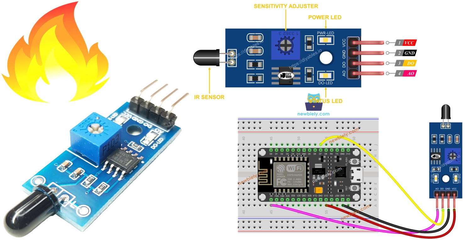
ESP8266 - Flame Sensor
The flame sensor is a nifty device that picks up and gauges the infrared emissions from flames, making it a handy tool for fire detection. You might also hear it referred to as an infrared flame sensor or a fire sensor. This sensor offers two types of outputs: a digital one (LOW/HIGH) and an analog one.
In this guide, we'll walk through using an ESP8266 along with a flame sensor to identify and measure flames and fires. Specifically, we'll go over the following steps:
- How to connect the flame sensor to an ESP8266.
- How to program the ESP8266 to spot flames and fires by interpreting the digital signal from the flame sensor.
- How to program the ESP8266 to gauge the flame level by interpreting the analog signal from the flame sensor.
Afterward, you can modify the code to activate a warning horn (via a relay) when it detects fire.
Hardware Preparation
Or you can buy the following kits:
| 1 | × | DIYables Sensor Kit (18 sensors/displays) |
Additionally, some of these links are for products from our own brand, DIYables .
Overview of Flame Sensor
The infrared flame sensor serves the purpose of identifying the existence of a flame or gauging the level of infrared emissions produced by the flame. This makes it a valuable tool for fire detection. The sensor offers two choices through a digital output pin and an analog output pin.
These infrared flame sensors are meticulously crafted to be discerning in the wavelengths of infrared radiation they pick up, concentrating on the specific wavelengths associated with flames. Their design aims to reduce the chances of false alarms triggered by other sources of infrared radiation, like human body heat or artificial lighting. Despite their precision, it's important to note that, like any sensor, they do have limitations. Under specific conditions, they may exhibit false positives or false negatives.
Pinout
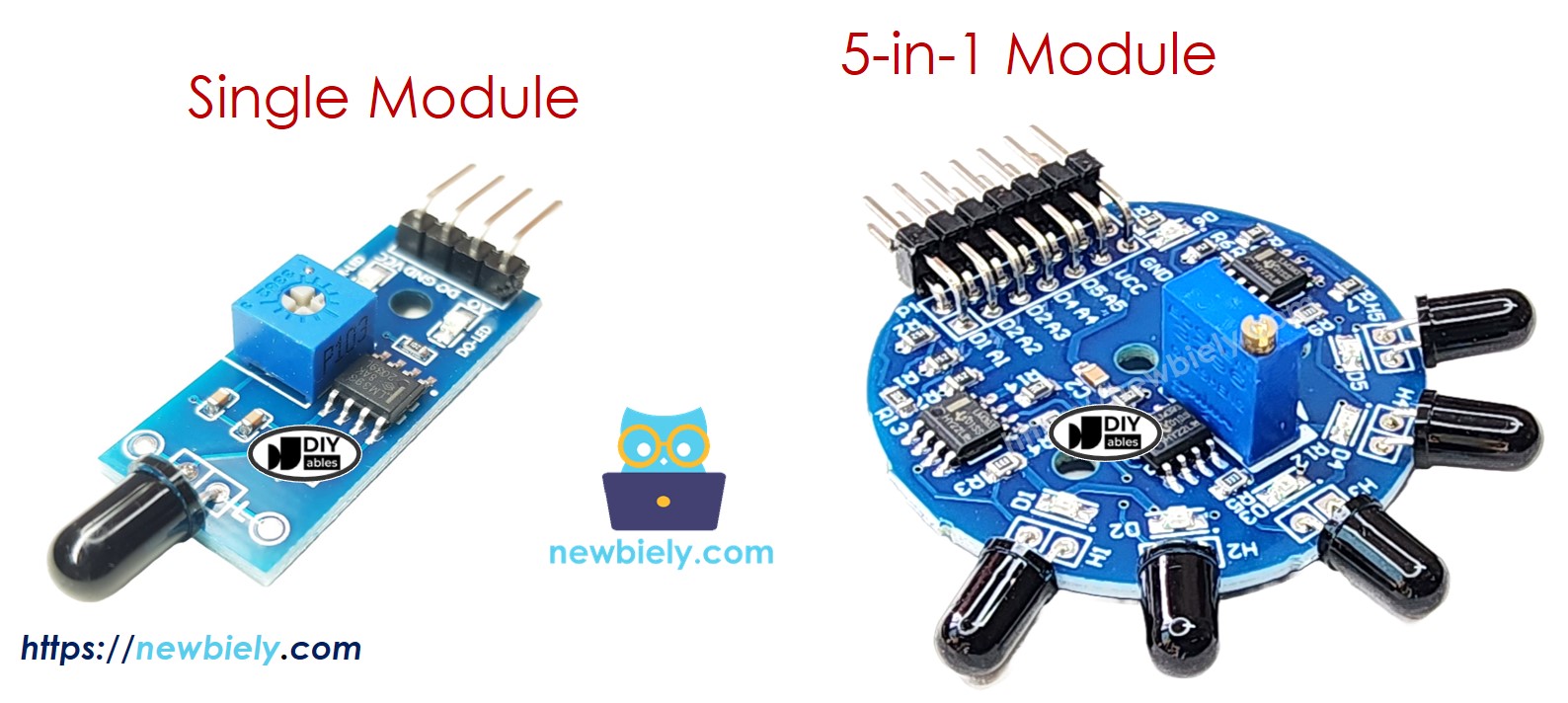
There are two types of flame sensor modules available:
A single flame sensor includes four pins:
- VCC pin: It needs to be connected to VCC (3.3V to 5V).
- GND pin: It needs to be connected to GND (0V).
- DO pin: It is a digital output pin. It is HIGH if the flame is not detected and LOW if detected. The threshold value for flame detection can be adjusted using a built-in potentiometer.
- AO pin: It is an analog output pin. The output value decreases as the infraed level is decreased, and it increases as infraed level is increased.
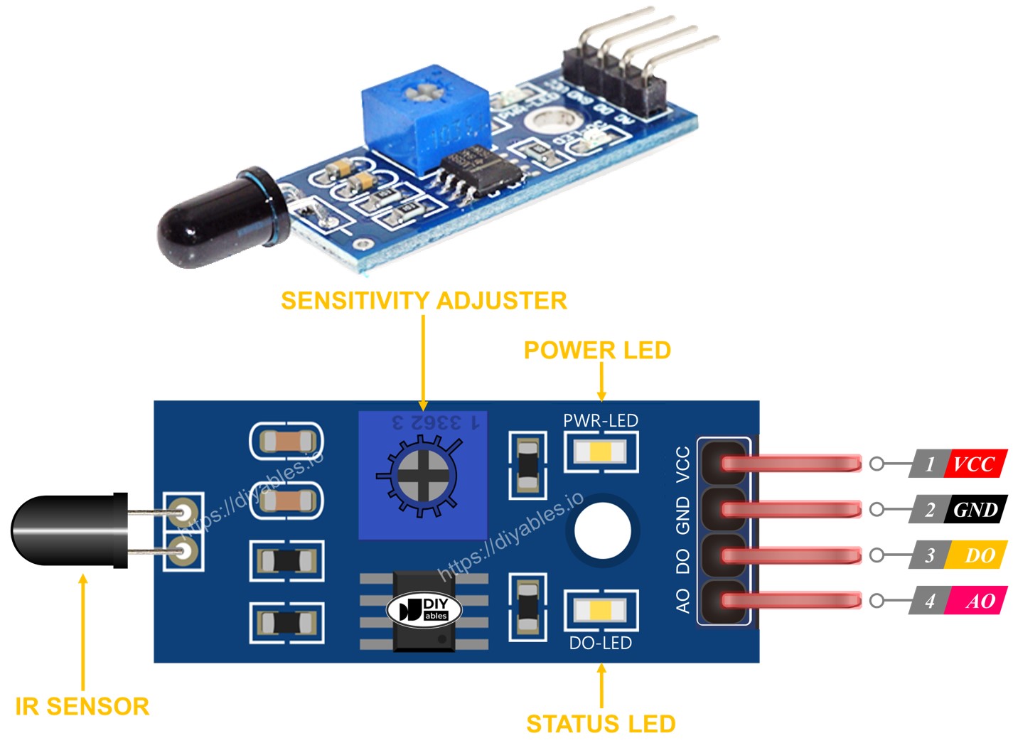
Furthermore, it has two LED indicators:
- One PWR-LED indicator for power.
- One DO-LED indicator for the flame state on the DO pin: it is on when flame is present.
The 5-in-1 flame sensor integrates five individual flame sensors onto a single PCB. These sensors share the same potentiometer, VCC, and GND connections. However, each sensor’s DO (Digital Output) and AI (Analog Input) pins operate independently from one another.
How It Works
For the Digital Output (DO) Pin:
- The module comes with a built-in dial that lets you adjust how sensitive it is to infrared light.
- If the infrared light is strong enough (passes the set sensitivity), it means the sensor has detected a flame. The output pin goes "LOW," and the DO-LED lights up.
- If the infrared light is not strong enough (below the set sensitivity), it means no flame is detected. The output pin goes "HIGH," and the DO-LED turns off.
For the Analog Output (AO) Pin:
- The AO pin gives you a number that represents how much infrared light is around.
- More surrounding infrared light gives you a higher number from the AO pin.
- Less surrounding infrared light gives you a lower number from the AO pin.
Keep in mind that adjusting the sensitivity with the dial doesn't change the value you get from the AO pin.
Wiring Diagram
Since the flame sensor module has two outputs, you can choose to use one or both of them, depending on what you need.
- The wiring diagram between ESP8266 and the flame sensor when using DO only.
This image is created using Fritzing. Click to enlarge image
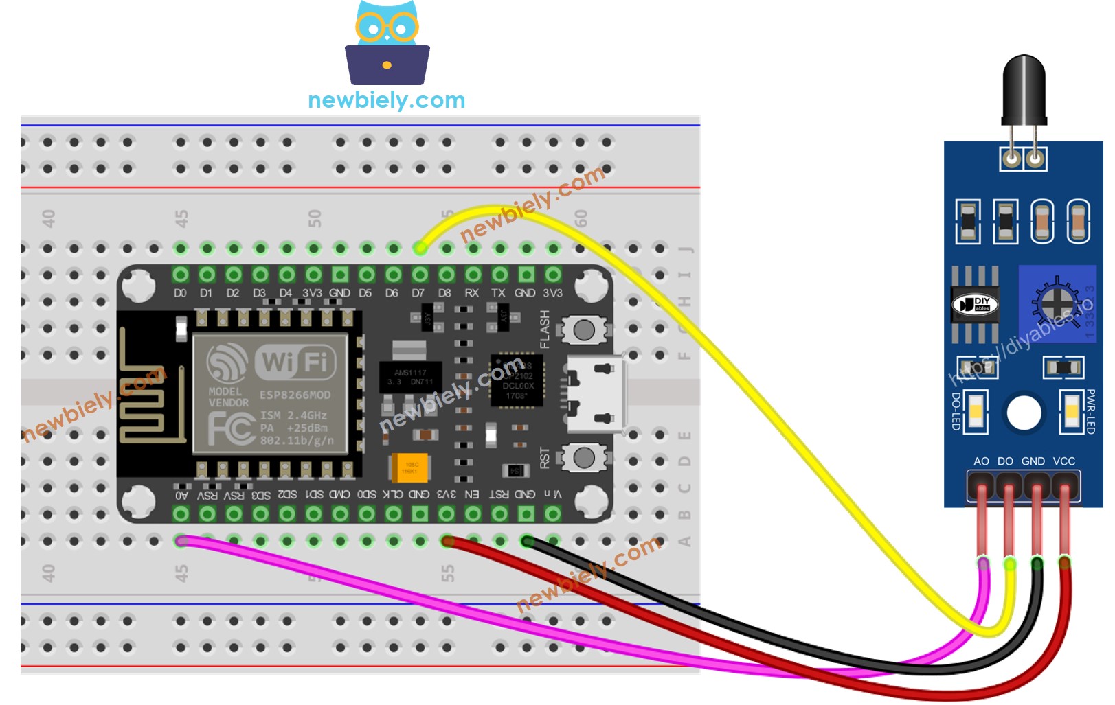
- The wiring diagram between ESP8266 and the flame sensor when using AO only.

This image is created using Fritzing. Click to enlarge image
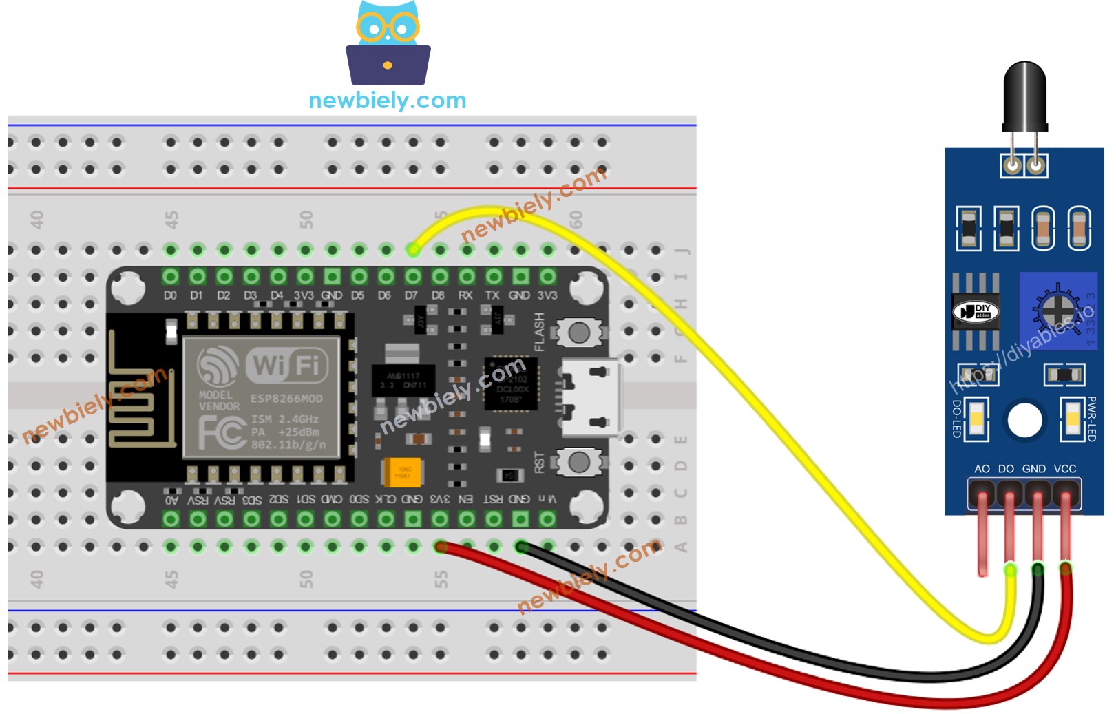
- The wiring diagram between ESP8266 and the flame sensor when using both AO an DO.
This image is created using Fritzing. Click to enlarge image
See more in ESP8266's pinout and how to supply power to the ESP8266 and other components.
ESP8266 Code - Read value from DO pin
Detailed Instructions
To get started with ESP8266 on Arduino IDE, follow these steps:
- Check out the how to setup environment for ESP8266 on Arduino IDE tutorial if this is your first time using ESP8266.
- Wire the components as shown in the diagram.
- Connect the ESP8266 board to your computer using a USB cable.
- Open Arduino IDE on your computer.
- Choose the correct ESP8266 board, such as (e.g. NodeMCU 1.0 (ESP-12E Module)), and its respective COM port.
- Copy the above code and open with Arduino IDE
- Click Upload button on Arduino IDE to upload code to ESP8266
- Direct the flame sensor to a flame.
- Check out the result on the Serial Monitor.
Please keep in mind that if you notice the LED status remaining on constantly or off even when the sensor faces to a flame, you can adjust the potentiometer to fine-tune the sensitivity of the sensor.
ESP8266 Code - Read value from AO pin
Detailed Instructions
- Wire the components as shown in the diagram.
- Connect the ESP8266 board to your computer using a USB cable.
- Open Arduino IDE on your computer.
- Choose the correct ESP8266 board, such as (e.g. NodeMCU 1.0 (ESP-12E Module)), and its respective COM port.
- Copy the above code and open with Arduino IDE
- Click Upload button on Arduino IDE to upload code to ESP8266
- Direct the flame sensor to a flame.
- Check out the result on the Serial Monitor.
※ NOTE THAT:
This tutorial uses the analogRead() function to get data from an ADC (Analog-to-Digital Converter) that's connected to a sensor or another part. The ESP8266's ADC works well for projects where you don't need very precise readings. But remember, the ESP8266's ADC isn't very accurate for detailed measurements. If your project needs to be very precise, you might want to use a separate ADC like the ADS1115 with the ESP8266, or use Arduino like the Arduino Uno R4 WiFi, which has a more reliable ADC.