ESP8266 - Ultrasonic Sensor - LCD
This tutorial instructs you how to use ESP8266 to obtain the distance from an ultrasonic sensor and show it on an LCD I2C display.
Hardware Preparation
Or you can buy the following kits:
| 1 | × | DIYables Sensor Kit (18 sensors/displays) |
Additionally, some of these links are for products from our own brand, DIYables .
Buy Note: Alternatively, you can assemble the LCD I2C display using LCD 1602 Display and PCF8574 I2C Adapter Module.
Overview of Ultrasonic Sensor and LCD
If you are unfamiliar with Ultrasonic sensor and LCD (pinout, how it works, how to program ...), the following tutorials will provide you with the necessary information:
Wiring Diagram
- If powering ESP8266 via USB port:
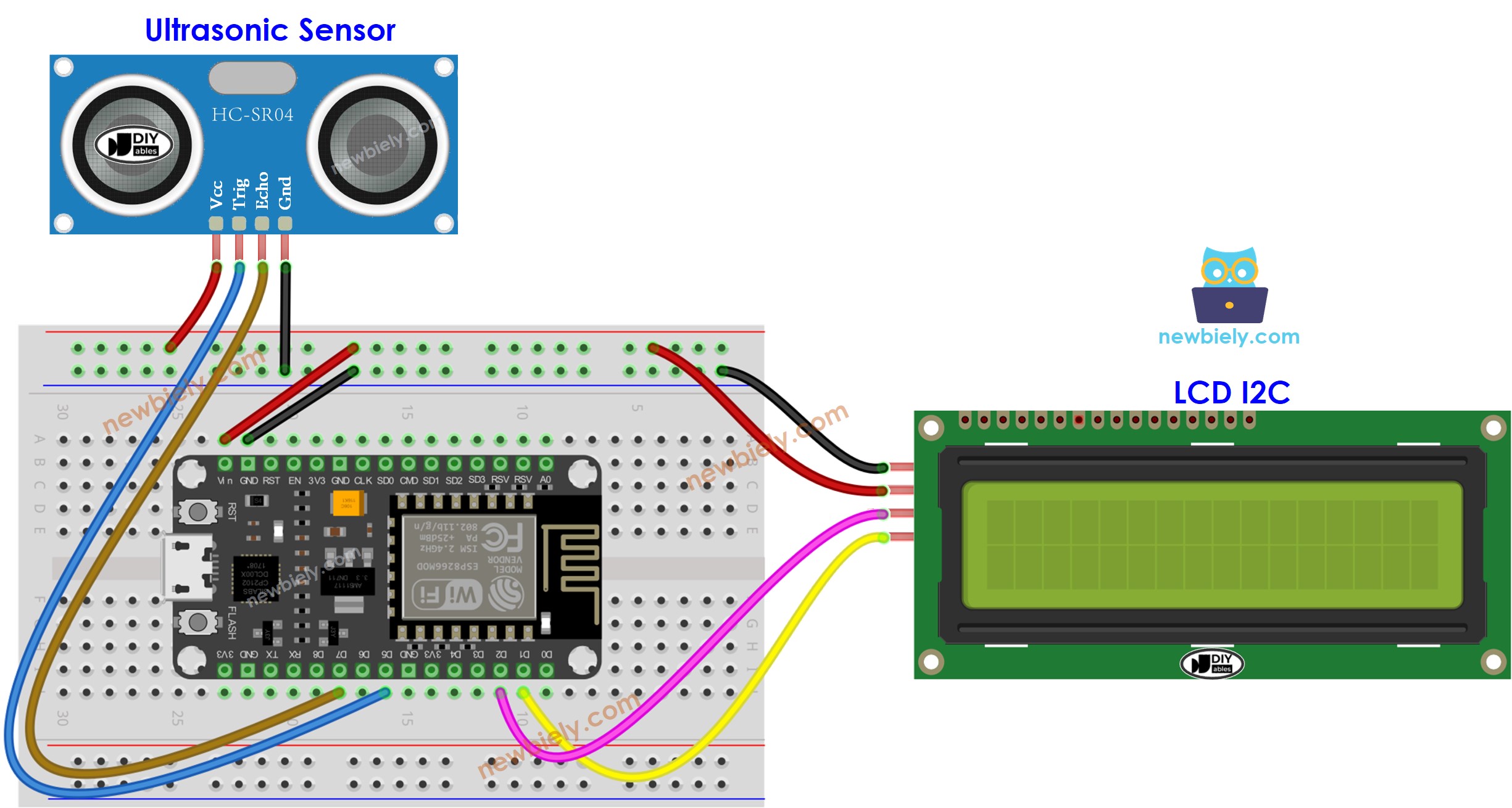
This image is created using Fritzing. Click to enlarge image
- If powering ESP8266 via USB port but power is not enough, use an external power source for LCD and sensor
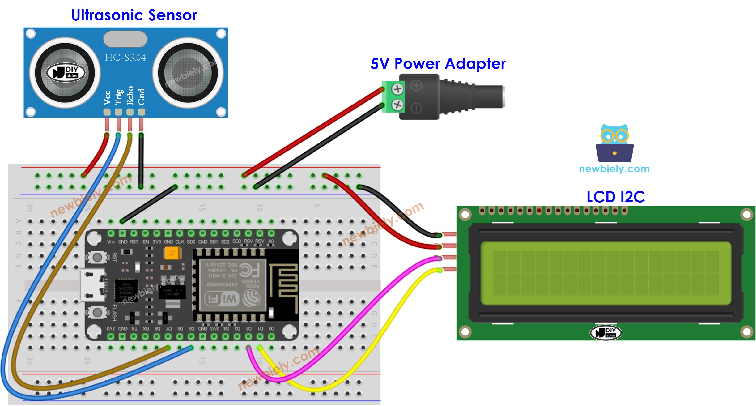
This image is created using Fritzing. Click to enlarge image
- If powering ESP8266 via Vin pin:
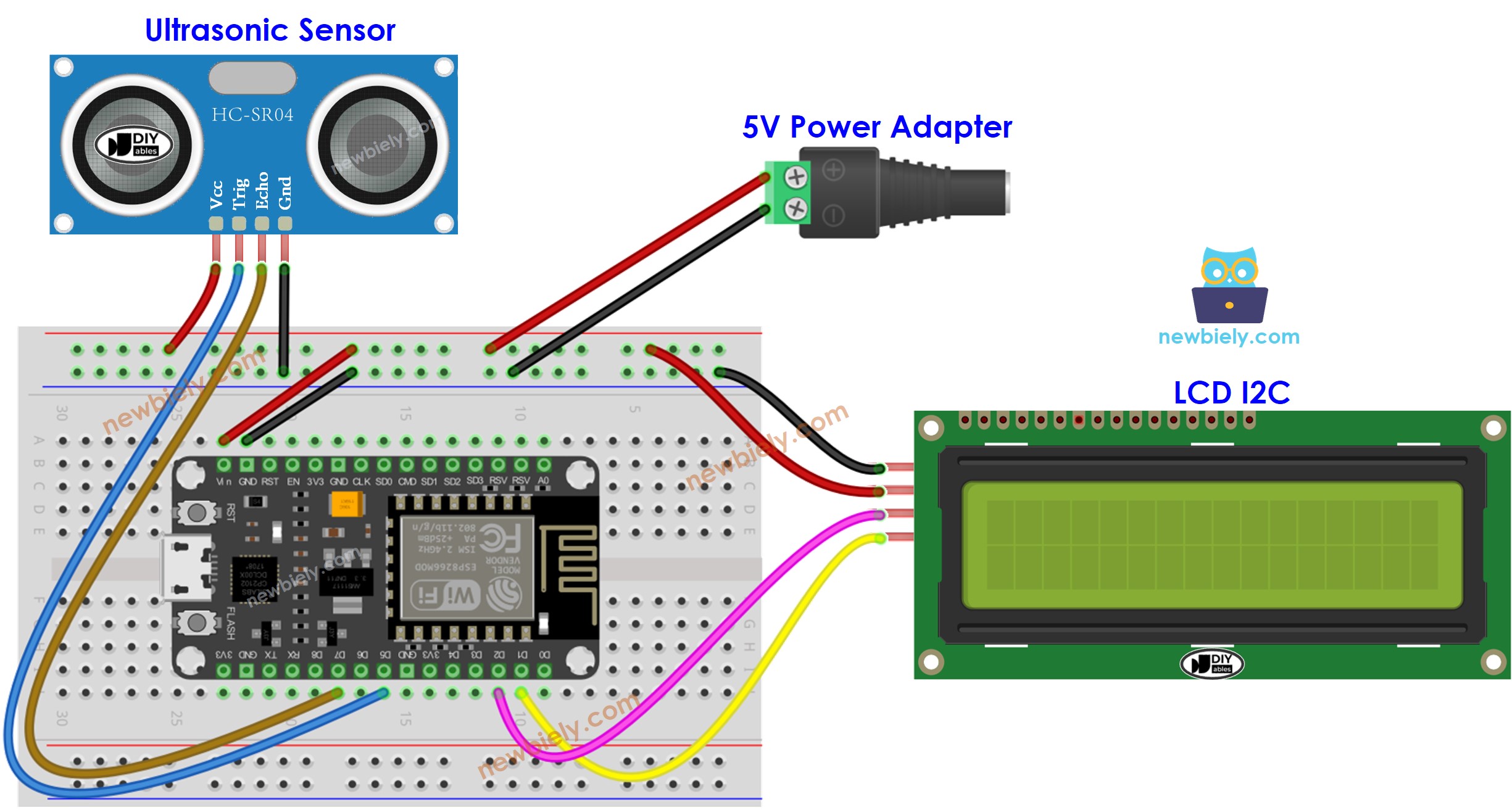
This image is created using Fritzing. Click to enlarge image
ESP8266 Code
※ NOTE THAT:
The I2C address of LCD can differ depending on the manufacturer. In our code, we used 0x27, which is specified by DIYables manufacturer.
Detailed Instructions
To get started with ESP8266 on Arduino IDE, follow these steps:
- Check out the how to setup environment for ESP8266 on Arduino IDE tutorial if this is your first time using ESP8266.
- Wire the components as shown in the diagram.
- Connect the ESP8266 board to your computer using a USB cable.
- Open Arduino IDE on your computer.
- Choose the correct ESP8266 board, such as (e.g. NodeMCU 1.0 (ESP-12E Module)), and its respective COM port.
- Attach the ESP8266 to your computer using a USB cable.
- Launch the Arduino IDE and select the correct board and port.
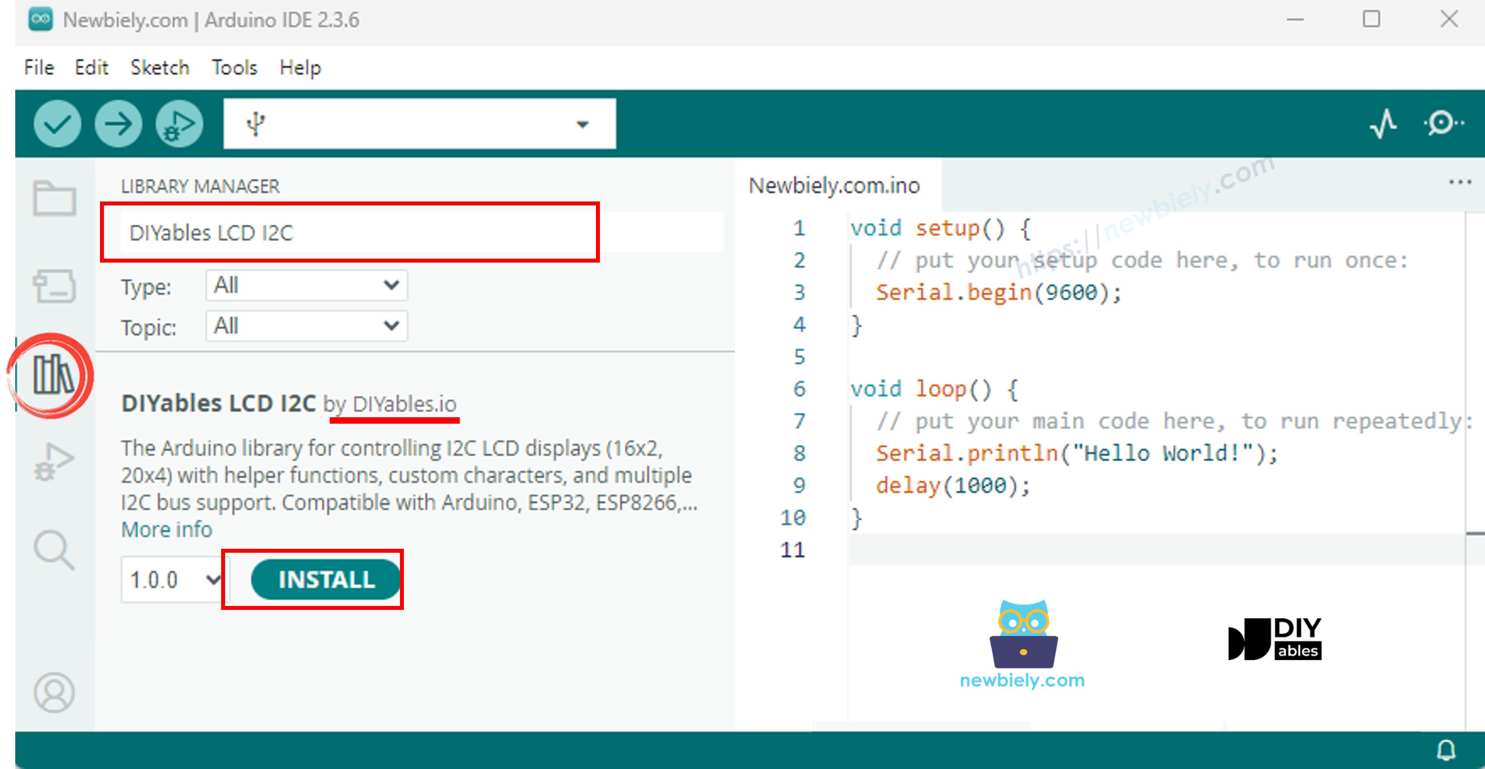
- Click to the Libraries icon on the left bar of the Arduino IDE.
- Search for “DIYables LCD I2C” and locate the DIYables_LCD_I2C library by DIYables.
- Then, press the Install button to install the library.
- Copy the code and open it with the Arduino IDE.
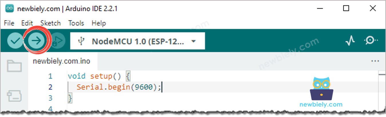
- Click the Upload button in the Arduino IDE to compile and upload the code to the ESP8266.
- Attach the sensor to both hot and cold water, or hold it in your hand.
- Check out the outcome displayed on the LCD.
This image is created using Fritzing. Click to enlarge image
See more in ESP8266's pinout and how to supply power to the ESP8266 and other components.
Code Explanation
Check out the line-by-line explanation contained in the comments of the source code!
※ NOTE THAT:
- If the LCD screen is not displaying anything, please refer to Troubleshooting on LCD I2C.
- The code provided is only for educational purposes. The ultrasonic sensor is very sensitive to noise, so if you plan to use it in a practical setting, you should filter out any noise. For more information on how to do this, please see how to filter noise for ultrasonic sensor.