ESP8266 Pinout
The ESP8266 offers the advantage of having a considerable number of GPIO pins at your need. However, it's crucial to pay close attention to the pinout details. Not all GPIO pins of ESP8266 are safe to use.
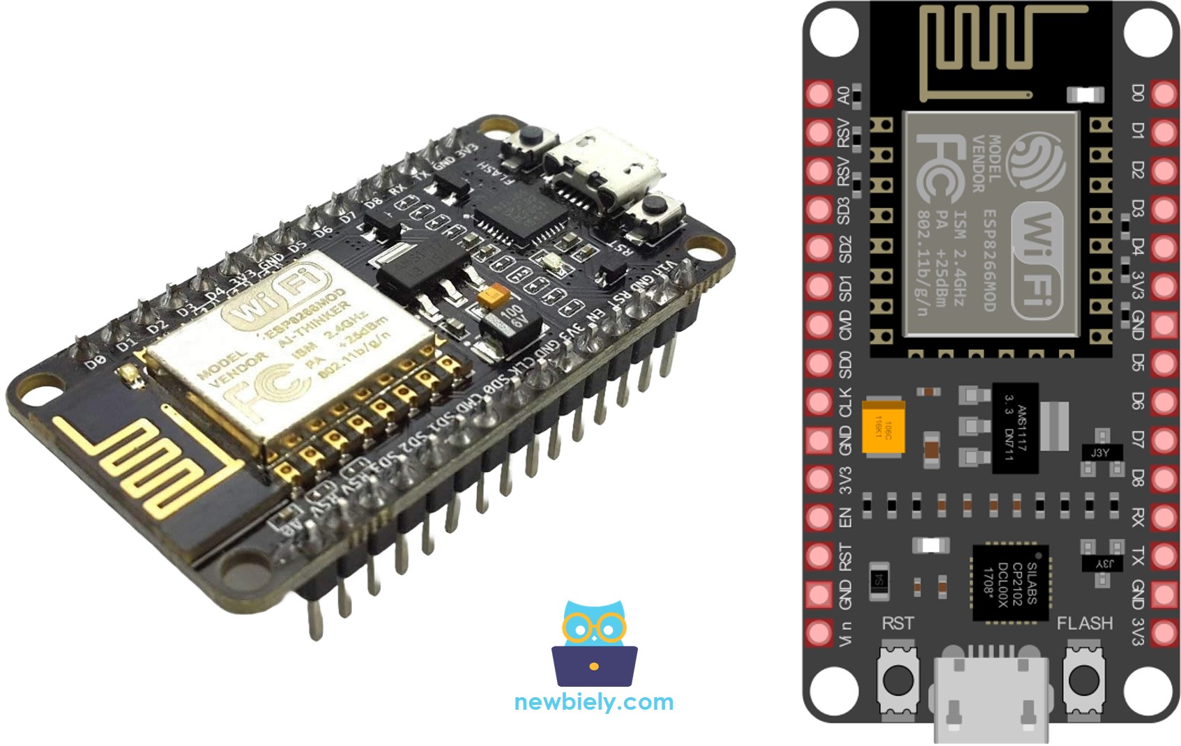
It's important to mention that the pinout reference provided below pertains to the widely used 30-pin ESP8266 NodeMCU development board.
Hardware Preparation
Or you can buy the following kits:
| 1 | × | DIYables Sensor Kit (18 sensors/displays) |
Additionally, some of these links are for products from our own brand, DIYables .
ESP8266 Peripherals and I/O
The ESP8266 NodeMCU boasts a total of 17 GPIO pins distributed across both sides of the development board through pin headers. These pins are versatile and can be assigned various peripheral functions, including:
- 9 x Digital input/output pins:
- 1 x ADC channel: Providing a single channel with 10-bit precision SAR ADC.
- 2 x UART interfaces: Featuring two UART interfaces with support for flow control.
- 4 x PWM outputs: Offering four PWM pins to regulate aspects like motor speed or LED brightness.
- 2 x SPI: Equipped with two SPI interfaces for connecting diverse sensors and peripherals.
- 1 x I2C: Incorporating one I2C interface for linking to a variety of sensors and peripherals.
- 1 x I2S: Including one I2S interface to incorporate sound into your project.
ESP8266 Pinout
The ESP8266 NodeMCU boasts a total of 30 pins, organized for user-friendly functionality. Check out the pinout diagram below to explore the layout:
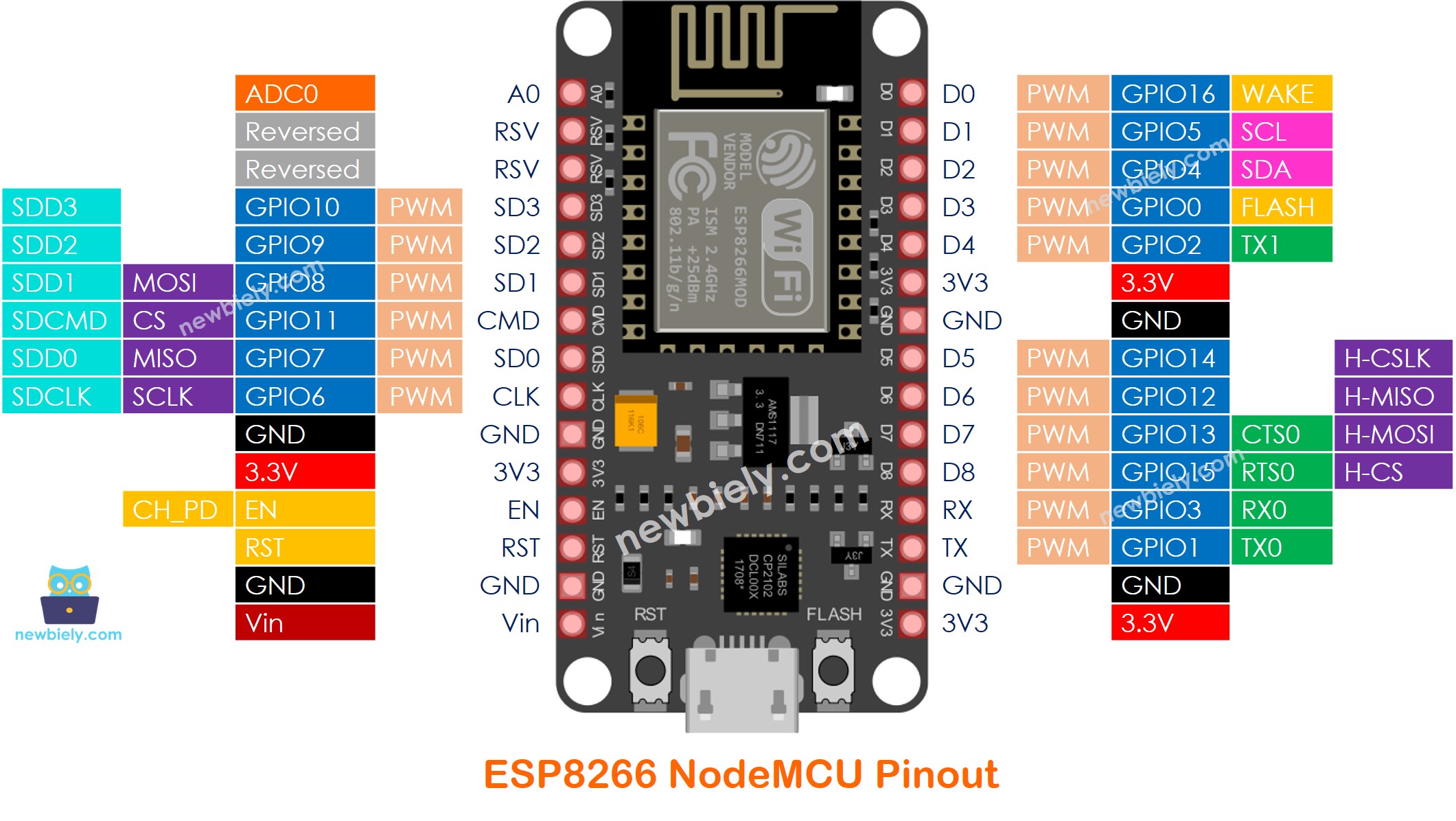
Now, let's dive into the individual pins of the ESP8266 and unravel their specific functions.
Digital Input/Output Pins
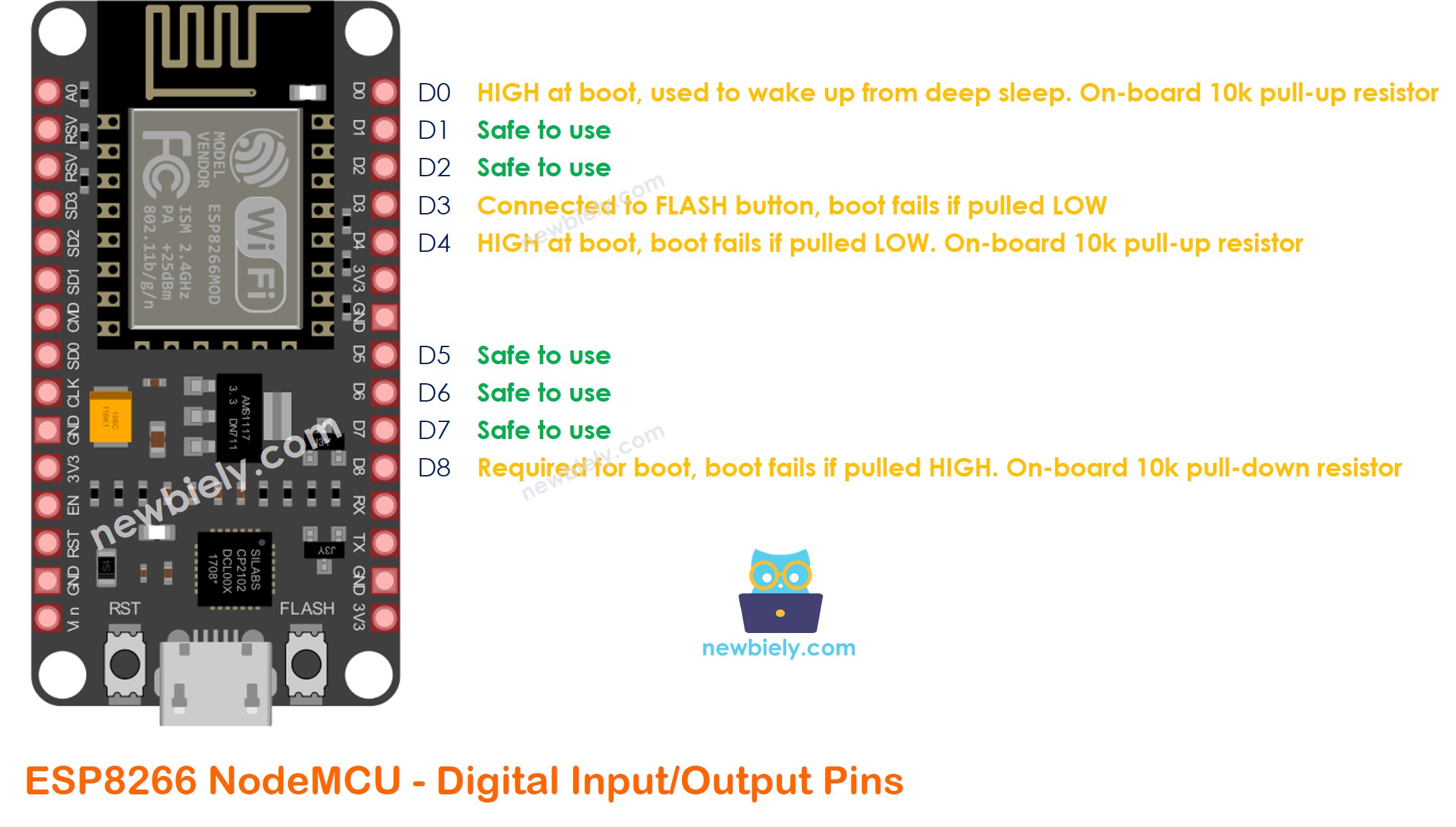
Among 30 pins of The ESP8266 NodeMCU board, you can use 9 pins for the digital input/output. Among these 9 pins, 5 pins are safe to use, the other 4 pins can also be used as digital input/output but with carefulness.
Within the 30 pins of the ESP8266 NodeMCU board, 9 pins can be used for digital input/output purposes. In details:
- 5 pins are safe for use as digital input/output pins
- 4 pins can also be used as digital input/output pins, but but require careful handling.
- All of 9 pins can be configured with internal (on-chip) pull-up or pull-down, or set to high impedance.
The table below shows which pins are safe to use and which pins should be used with caution.
| GPIO | Pin Label | Safe to use? | Reason |
|---|---|---|---|
| GPIO16 | D0 | HIGH at boot, used to wake up from deep sleep | |
| GPIO5 | D1 | ||
| GPIO4 | D2 | ||
| GPIO0 | D3 | connected to FLASH button, boot fails if pulled LOW. On-board 10k external pull-up resistor | |
| GPIO2 | D4 | HIGH at boot, boot fails if pulled LOW. On-board 10k external pull-up resistor | |
| GPIO14 | D5 | ||
| GPIO12 | D6 | ||
| GPIO13 | D7 | ||
| GPIO15 | D8 | Required for boot, boot fails if pulled HIGH. On-board 10k external pull-down resistor | |
| GPIO3 | RX | RX pin, used for flashing and debugging | |
| GPIO1 | TX | TX pin, used for flashing and debugging | |
| GPIO6 | CLK | Connected to Flash memory | |
| GPIO7 | SDO | Connected to Flash memory | |
| GPIO11 | CMD | Connected to Flash memory | |
| GPIO8 | SD1 | Connected to Flash memory | |
| GPIO9 | SD2 | Connected to Flash memory | |
| GPIO10 | SD3 | Connected to Flash memory | |
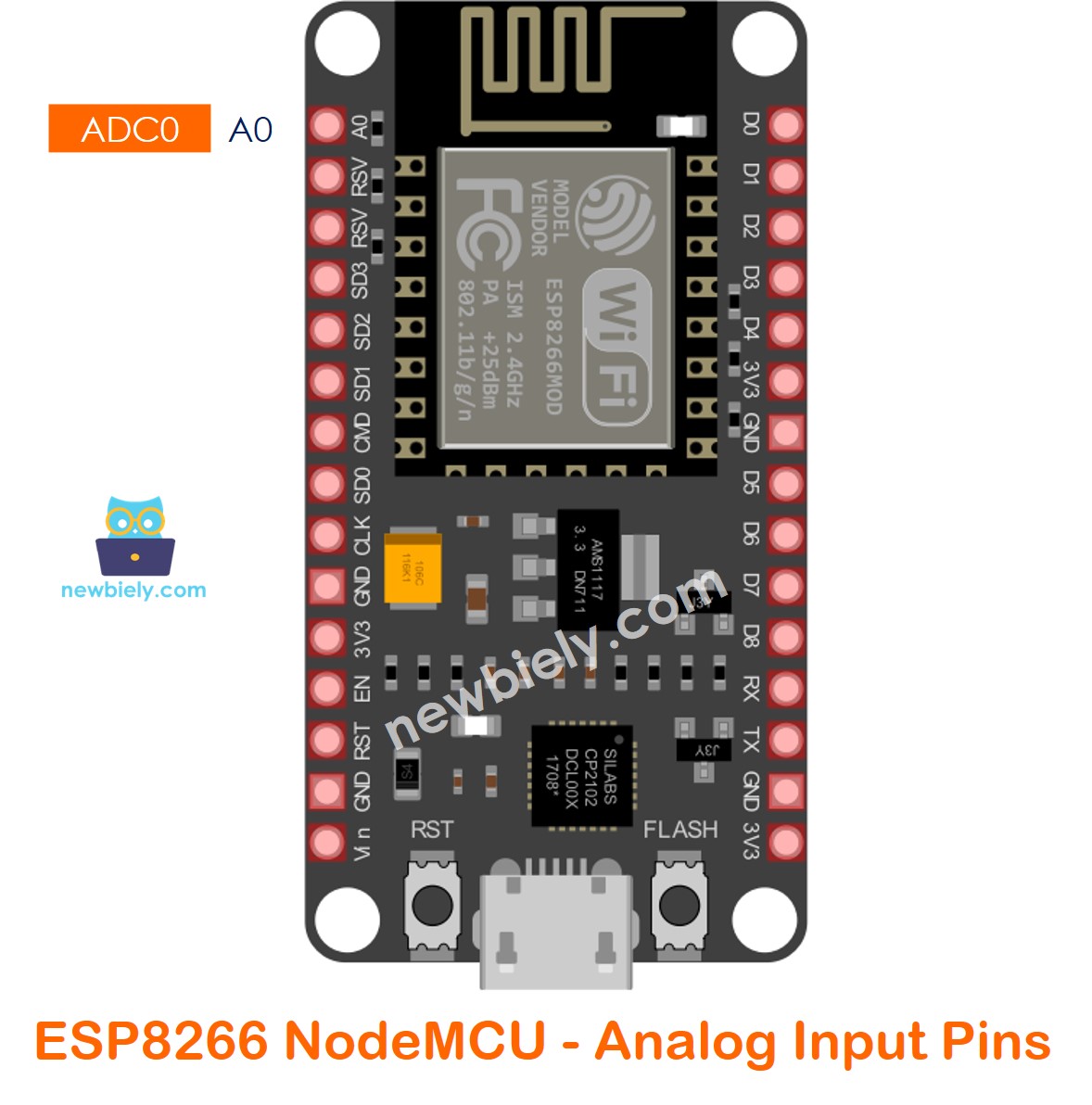
| ADC0 | A0 | Can be used as the analog input pin only. |
| Legend | |
|---|---|
| These are your top-priority pins, absolutely safe for use. No concerns here. | |
| Pay close attention because their behavior, particularly during boot, can be unpredictable. Also pay attention to their on-board external pull-up/pull-down resistors. Use them only when absolutely necessary. | |
| These pins should NOT be used as digital input/output pins. |
The image below shows which GPIO pins can be used as digital input/output pins.
How to program for ESP8266 digital input/output pins.
You can use the following functions to manipulate the ESP8266's digital input/output pins.
Please note that you need to use the pin label in the code. For example, pin GPIO5 (D1):
Examples of using the ESP8266's digital input pin:
Examples of using the ESP8266's digital output pin:
ADC Pins
The ESP8266 comes equipped with a 10-bit precision Analog-to-Digital Converter (ADC), allowing it to discern 1024 (2^10) distinct analog levels. Essentially, it converts input voltages within the 0 to 3.3V range (operating voltage) into integer values spanning from 0 to 1024. Consequently, this configuration yields a resolution of 3.3 volts divided by 1024 units, equivalent to 0.0032 volts (3.2 mV) per unit.
Example code of using ADC on ESP8266:
Examples of the analog sensors that uses ESP8266's A0 pin:
SPI Pins
ESP8266 features two SPIs (SPI, and HSPI) in slave and master modes. These SPIs also support the general-purpose SPI features listed below:
- 4 timing modes of the SPI format transfer
- Up to 80 MHz and the divided clocks of 80 MHz
- Up to 64-Byte FIFO
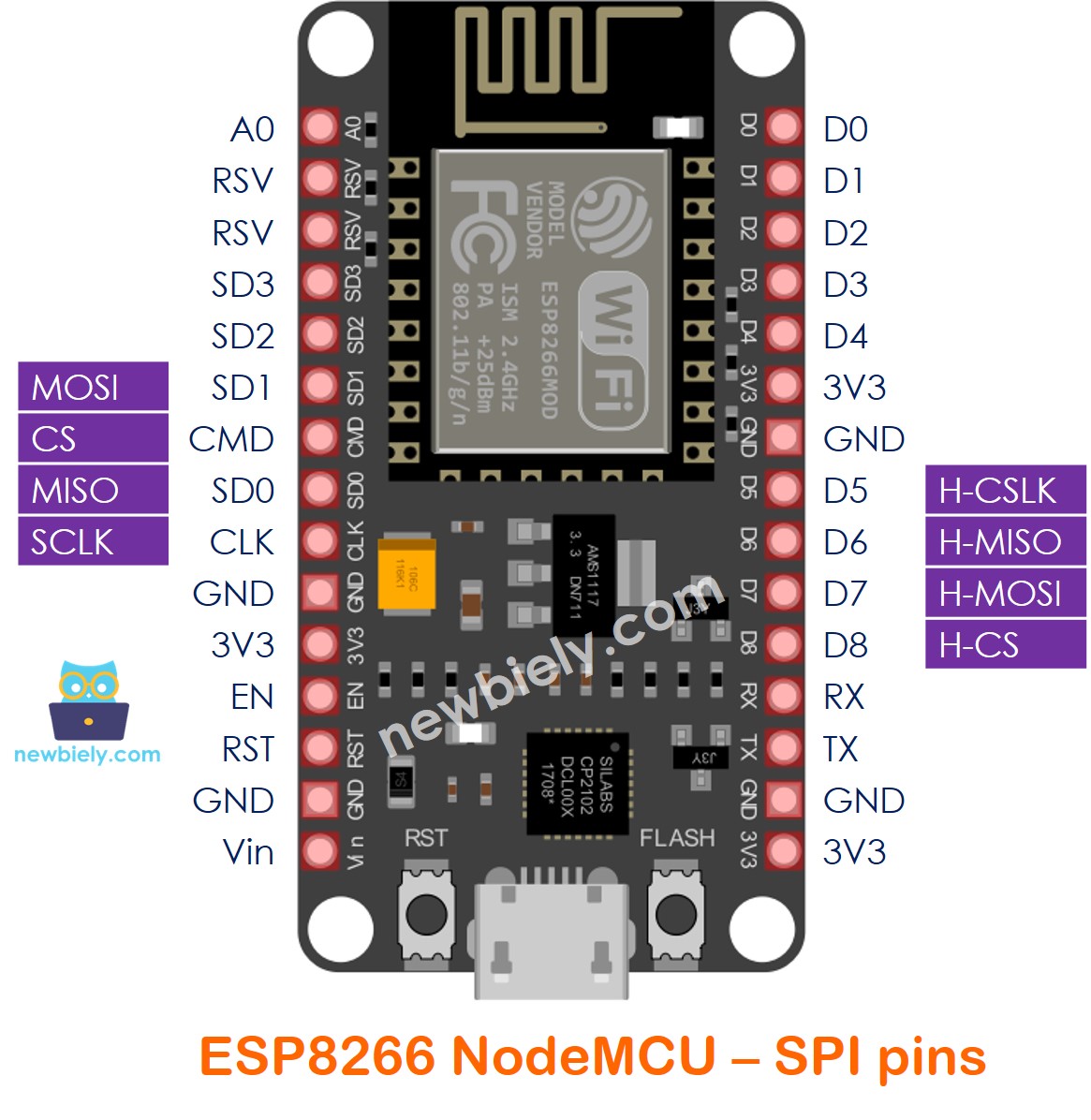
Examples of using the ESP8266's SPI pins:
I2C Pins
The ESP8266 doesn't have built-in I2C pins, but you can still make it work through 'bitbanging.' It performs well, and the ESP8266 is speedy enough to keep up with the performance expected from Arduino.
By default, GPIO4 (SDA) and GPIO5 (SCL) are set up as I2C pins to simplify things for those using existing Arduino code, libraries, and sketches.
However, you have the freedom to choose any other two GPIO pins for I2C by using wire.begin(SDA, SCL) in the Arduino IDE.
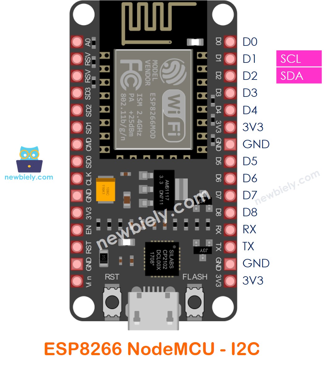
Examples of using the ESP8266's I2C pins:
UART Pins
The ESP8266 boasts two UART interfaces, UART0 and UART2, which enable asynchronous communication (RS232 and RS485) at impressive speeds of up to 4.5 Mbps. This capability makes them well-suited for high-speed data transfer applications.
- UART0 (TXD0, RXD0, RST0, and CTS0 pins) is used for communication.
- UART1 (TXD1 pin) only features a data transmit signal and is typically used for printing logs.
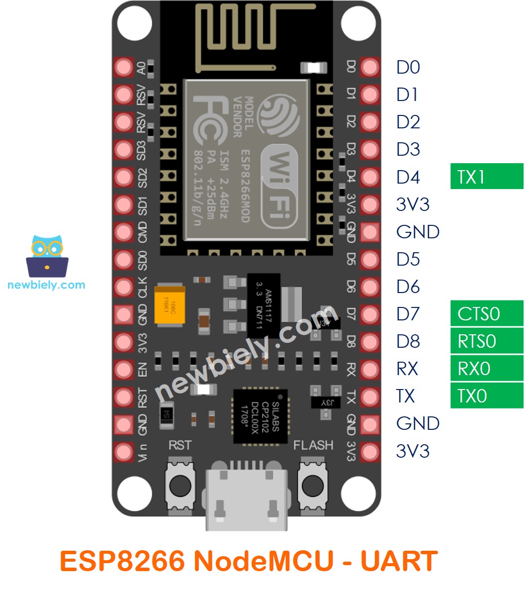
RXD0 and TXD0 serve as the serial control and bootloading pins for the ESP module, playing a crucial role in communication with the module. They are especially important during the bootloading process. Therefore, you should use caution when using these since they are connected through to the USB-to-serial converter and will therefore receive USB traffic.
PWM Pins
Every GPIO pin on the ESP8266, spanning from GPIO0 to GPIO15, is programmable to generate pulse width modulated (PWM) outputs.
The PWM signal on the ESP8266 boasts a 10-bit resolution, offering precise control over the output. Additionally, the PWM frequency range is customizable, ranging from 1000 μs to 10000 μs, equivalent to a flexible frequency span between 100 Hz and 1 kHz. This adaptability makes it suitable for a wide range of applications requiring varied PWM settings.
Power Pins
- The VIN pin offers a convenient option to directly power the ESP8266 and its peripherals when supplied with a regulated 5V power source.
- The 3V3 pin serves as the output from the on-board voltage regulator, capable of providing a substantial 600mA. This makes it a reliable source for powering connected devices and components.
- GND functions as the ground pin, establishing the electrical reference point for the ESP8266 and connected devices. It ensures a common ground for the system, maintaining stable and proper electrical connections.
Interrupt Pins
Every GPIO (General Purpose Input/Output) on the ESP8266, with the exception of GPIO16, is configurable as an interrupt.
This means that each GPIO, from GPIO0 to GPIO15, can be set up to trigger an interrupt, allowing the ESP8266 to respond to specific events or changes in input states. GPIO16, however, does not support this interrupt configuration. This flexibility in interrupt usage enhances the ESP8266's versatility in handling real-time events and interactions with external devices.
SDIO Pins
The ESP8266 is equipped with a single slave SDIO (Secure Digital Input/Output Interface) designed for connecting SD cards. It supports both SDIO v1.1 at 4-bit 25 MHz and SDIO v2.0 at 4-bit 50 MHz.
This feature enables seamless integration of SD cards with the ESP8266, providing high-speed data transfer capabilities and compatibility with different SDIO versions. Whether utilizing SDIO v1.1 or v2.0, the ESP8266 offers versatility for connecting and accessing data from SD cards efficiently.
Control Pins
- The EN (also known as CH_PD or Chip Power Down) pin acts as the enable pin for the ESP8266 and is pulled high by default. When set to HIGH, the chip is enabled, allowing normal operation. Conversely, when pulled LOW, the chip is disabled, effectively powering it down.
- The RST pin functions as the reset pin for the ESP8266, and it is pulled high by default. When briefly pulled down to ground, it triggers a reset for the ESP8266, similar to pressing the on-board RST button.
- The FLASH pin is utilized by the ESP8266 to determine whether to boot into the bootloader. Holding the pin low during power-up initiates the bootloading process, akin to pressing the on-board FLASH button.
- The WAKE pin is employed to wake the ESP8266 from deep sleep mode, allowing the device to resume normal operation after being in a low-power state.