ESP8266 - Solenoid Lock
The Solenoid Lock, also referred to as the Electric Strike Lock, can be used to lock and unlock cabinets, drawers, and doors. This tutorial will teach us how to control the solenoid lock using ESP8266.
An alternative to the Solenoid Lock is the Electromagnetic Lock. For more information, please refer to the ESP8266 - Electromagnetic Lock tutorial.
Hardware Preparation
Or you can buy the following kits:
| 1 | × | DIYables Sensor Kit (18 sensors/displays) |
Additionally, some of these links are for products from our own brand, DIYables .
Overview of Solenoid Lock
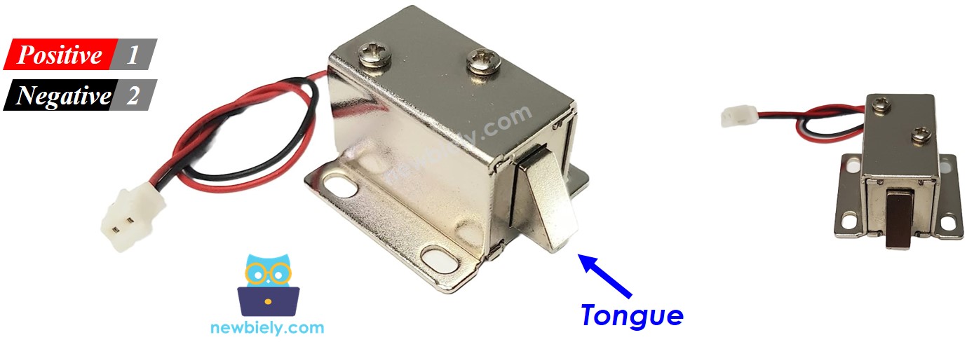
The Solenoid Lock Pinout
The Solenoid Lock consists of two wires:
- The Positive (+) wire (red) should be connected to the 12V of a DC power supply
- The Negative (-) wire (black) should be connected to the GND of a DC power supply
How It Works
- When supplying power to the solenoid lock, the lock tongue is extended, resulting in the door being locked.
- When NOT supplying power to the solenoid lock, the lock tongue is retracted, resulting in the door being unlocked.
※ NOTE THAT:
The solenoid lock typically requires a 12V, 24V or 48V power source. Consequently, it CANNOT be connected directly to an ESP8266 pin. A relay must be used to link the solenoid lock to the ESP8266 pin.
If the solenoid lock is connected to a relay (in a normally open mode):
- When the relay is not activated, the door is unlocked
- When the relay is activated, the door is locked
Connecting ESP8266 to a relay enables programming for ESP8266 to control the solenoid lock. For more information on relays, please refer to the ESP8266 - Relay tutorial.
Wiring Diagram
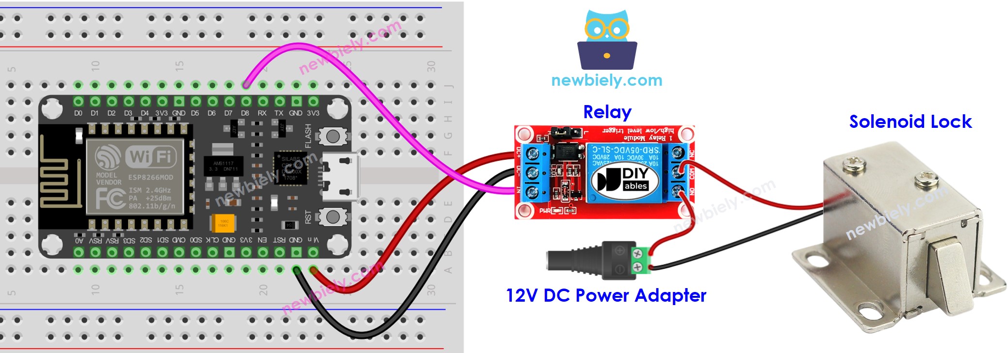
This image is created using Fritzing. Click to enlarge image
ESP8266 Code
This code causes the door to be locked and unlocked every five seconds.
Detailed Instructions
To get started with ESP8266 on Arduino IDE, follow these steps:
- Check out the how to setup environment for ESP8266 on Arduino IDE tutorial if this is your first time using ESP8266.
- Wire the components as shown in the diagram.
- Connect the ESP8266 board to your computer using a USB cable.
- Open Arduino IDE on your computer.
- Choose the correct ESP8266 board, such as (e.g. NodeMCU 1.0 (ESP-12E Module)), and its respective COM port.
- Copy the code and open it in the Arduino IDE.
- Click the Upload button in the Arduino IDE to send the code to the ESP8266.
- Check out the state of the lock tongue.
ESP8266 - Button Controls Solenoid Lock
- Diagram of Wiring
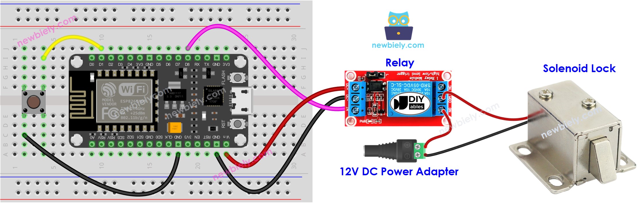
This image is created using Fritzing. Click to enlarge image
See more in ESP8266's pinout and how to supply power to the ESP8266 and other components.
- Writing code for an ESP8266 board.
Detailed Instructions
- Wire the components as shown in the diagram.
- Connect the ESP8266 board to your computer using a USB cable.
- Open Arduino IDE on your computer.
- Choose the correct ESP8266 board, such as (e.g. NodeMCU 1.0 (ESP-12E Module)), and its respective COM port.
- Install the ezButton library. Refer to How To for instructions.
- Copy the code and open it in the Arduino IDE.
- Click the Upload button on the Arduino IDE to upload the code to the ESP8266.
- Push the button once.
- Check out the lock tongue's state for 10 seconds.
※ NOTE THAT:
In the code above, we used the delay function. As a result, we do not have to implement debouncing for the button. Nevertheless, we still included the code with debouncing in case you would like to carry out additional tasks without using the delay function. Check out How to use millis() instead of delay() for more information.