ESP8266 - BLE
This tutorial instructs you how to use ESP8266 to control BLE HM-10 Module. In detail, we will learn:
- The utilization of Bluetooth Low Energy (BLE) technology with ESP8266
- Sending data from ESP8266 to a smartphone app via BLE
- Receiving data on ESP8266 from a smartphone app through BLE
- Controlling ESP8266 from a smartphone app with the help of BLE.
The purpose of this tutorial is to:
- Exchange data between an ESP8266 and a smartphone app via BLE.
- Utilize the widely popular HM-10 Bluetooth Low Energy module.
- Showcase the Bluetooth Serial Monitor app on Android, but any Android/iOS app can be used.
- Manipulate various devices connected to ESP8266 through the smartphone app, with examples such as an LED and servo motor.
It is important to be aware that this tutorial is specifically about Bluetooth Low Energy (BLE, or Bluetooth 4.0). If you need information on Classic Bluetooth (Bluetooth 2.0), please consult a similar tutorial ESP8266 - Bluetooth.
Hardware Preparation
Or you can buy the following kits:
| 1 | × | DIYables Sensor Kit (18 sensors/displays) |
Additionally, some of these links are for products from our own brand, DIYables .
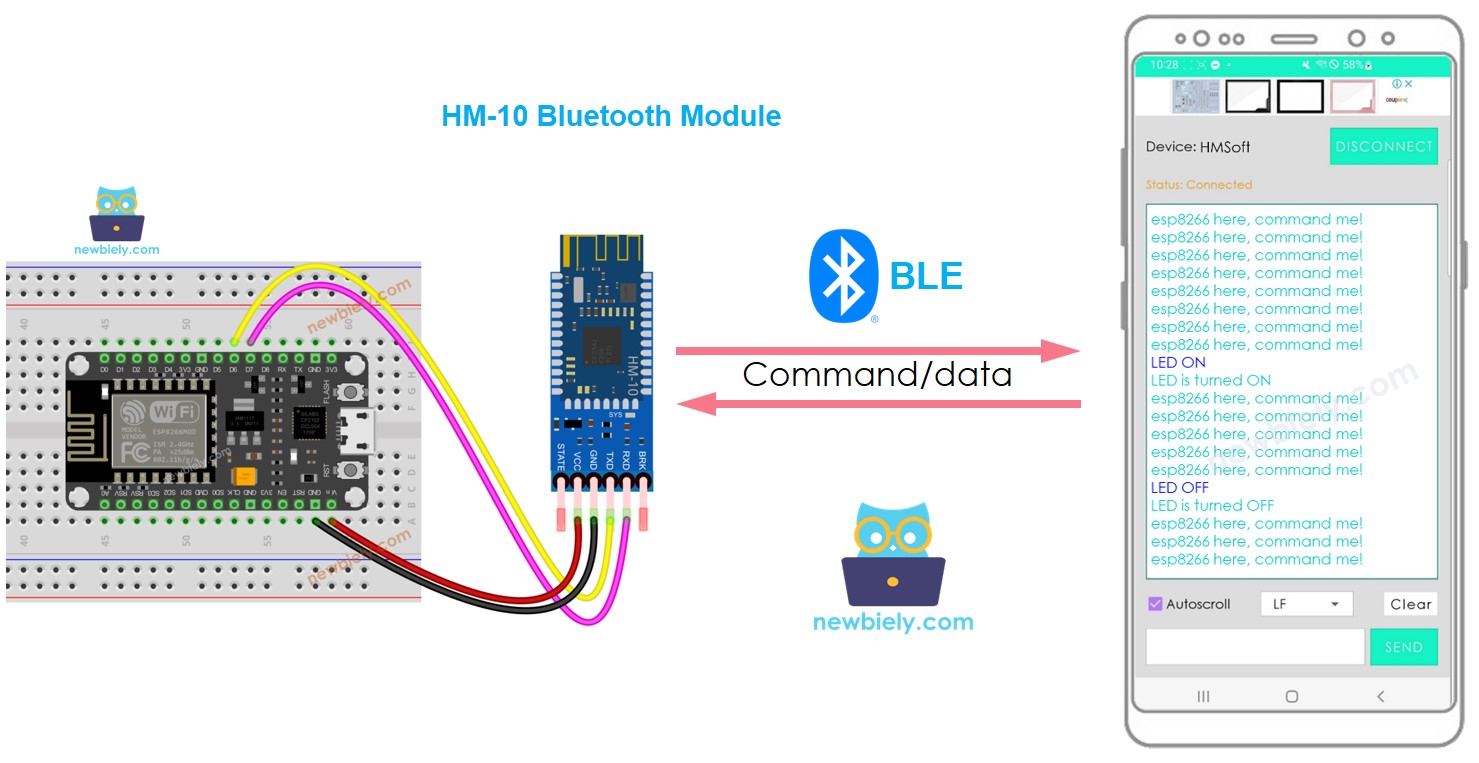
Overview of HM-10 Bluetooth Module
The HM-10 is a Serial BLE module that works as a Serial to Bluetooth Low Energy adapter. It carries out the following tasks:
- Taking data from the Serial RX pin and sending it to a connected device, like a smartphone, through BLE
- Receiving data from BLE (from the paired device) and transmitting it to the Serial TX pin.
When an ESP8266 is used to communicate with a smartphone app (Android/iOS), the following steps take place:
- A connection is established between the ESP8266 and the HM-10 Bluetooth module via Serial/SoftwareSerial pins
- The HM-10 Bluetooth module is paired with the smartphone app
- Data is sent from the ESP8266 to the smartphone app by sending it to the Serial/SoftwareSerial
- Data is received from the smartphone app by the ESP8266 by reading it from the Serial/SoftwareSerial
- No extra BLE code is needed on the ESP8266.
The BLE HM-10 Module Pinout
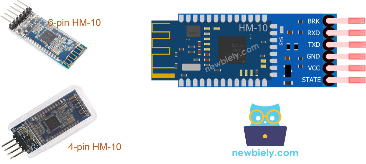
The HM-10 BLE Module has 6 pins:
- The BKR pin is used to control the behavior of the module. If you are a beginner, you can ignore this pin.
- The RX pin is the serial data pin and should be connected to the TX pin of ESP8266. Data received from this pin will be sent to Bluetooth.
- The TX pin is the serial data pin and should be connected to the RX pin of ESP8266. Data received via BLE will be sent to this pin as serial data.
- The GND pin is the power pin and should be connected to the GND of the power source.
- The VCC pin is the power pin and should be connected to 3.3V of Supply voltage.
- The STATE pin indicates the working states:
- Blink in standby mode - it will repeat 500ms pulse;
- On in connection state - it will be at a high level.
- Only four pins are necessary for the HM-10: VCC, GND, RX, and TX.
- Some producers of the HM-10 manufacture it with only these four pins.
※ NOTE THAT:
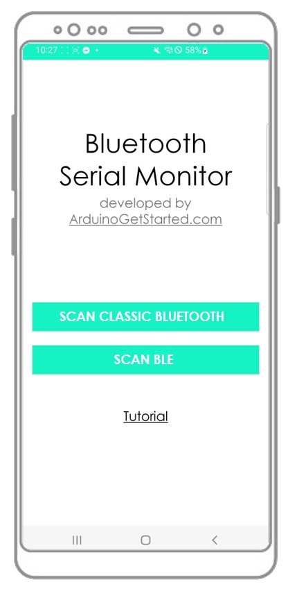
Overview of Bluetooth Serial Monitor App
To use the Bluetooth Serial Monitor App, you must first connect the ESP8266 to an HM-10 Bluetooth module. Then, download and install the app on your smartphone. Finally, open the app and connect it to the HM-10 Bluetooth module.
Once you have finished these steps, you will be able to transmit and receive data from the ESP8266 as if you were using the Serial Monitor in the Arduino IDE, without needing to make any changes to your ESP8266 code or add any code related to Bluetooth.
Wiring Diagram
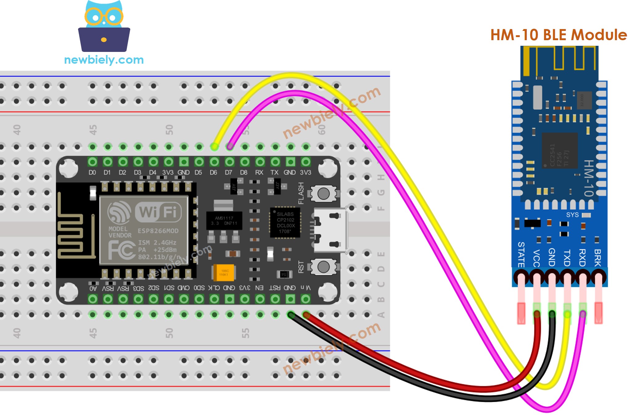
This image is created using Fritzing. Click to enlarge image
See more in ESP8266's pinout and how to supply power to the ESP8266 and other components.
A wiring table is a type of chart that displays the connections between different components. A wiring table is a chart that shows the links between various components.
| ESP8266 Pins | HM-10 Bluetooth Pins |
|---|---|
| Pin D7 | TX |
| Pin D6 | RX |
| 5V | VCC |
| GND | GND |
| BKR (NOT connected) | |
| STATE (NOT connected) |
※ NOTE THAT:
The ESP8266 code can be modified to use other pins by substituting the Serial object with an alternate option, such as Serial1, Serial2, or SoftwareSerial (if available).
How To Program For Bluetooth
No special programming for Bluetooth is required; only Serial programming is necessary.
ESP8266 sends data to Bluetooth App on Smartphone
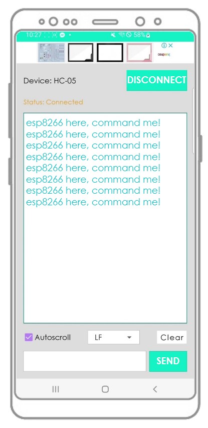
To send data from an ESP8266 board to a Bluetooth app on a smartphone, the following code can be used. This example shows the transmission of the message “ESP8266 here, command me!” from the ESP8266 to the smartphone app every second.
Detailed Instructions
To get started with ESP8266 on Arduino IDE, follow these steps:
- Check out the how to setup environment for ESP8266 on Arduino IDE tutorial if this is your first time using ESP8266.
- Wire the components as shown in the diagram.
- Connect the ESP8266 board to your computer using a USB cable.
- Open Arduino IDE on your computer.
- Choose the correct ESP8266 board, such as (e.g. NodeMCU 1.0 (ESP-12E Module)), and its respective COM port.
To set up an ESP8266 board to communicate with a smartphone via BLE, these steps should be followed:
- Obtain the Bluetooth Serial Monitor App and install it on your smartphone.
- Connect the HM-10 Bluetooth module to the ESP8266 board as per the wiring diagram.
- Open the Arduino IDE, copy the code given above, and upload it to the ESP8266 board. If you are unable to upload the code, disconnect the TX and RX pins from the Bluetooth module, upload the code, and then reconnect the RX/TX pins.
- Launch the Serial Monitor on the Arduino IDE.
- On your smartphone, open the Bluetooth Serial Monitor App and select the BLE mode.
- Connect the smartphone to the HM-10 Bluetooth module.
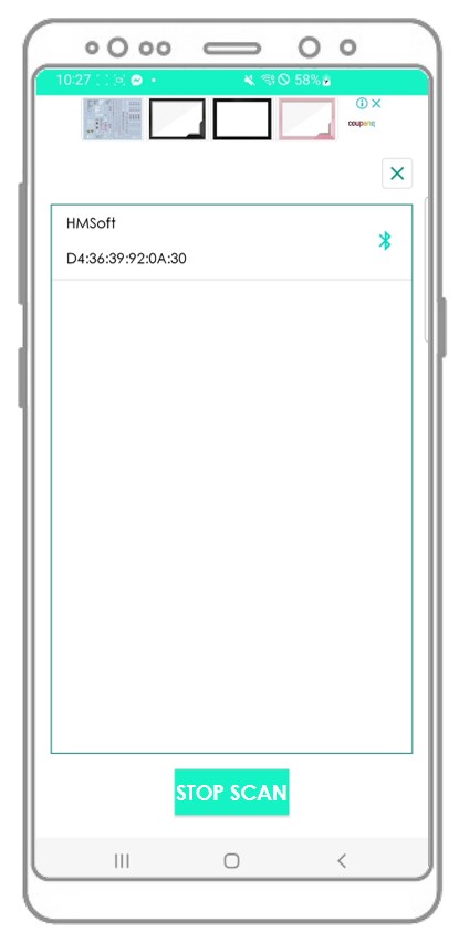
- Examine the outcome of the Android App.
- Examine the output shown on the Serial Monitor of the Arduino IDE.
If you take the steps mentioned and execute the code, you will notice that the data shown on the Serial Monitor of the Arduino IDE and the Android app are the same.
Bluetooth App Send data To ESP8266
The following steps are taken by the code:
- Transmit data from the Bluetooth app to the ESP8266 board
- The ESP8266 board reads the incoming data and sends a response back to the Bluetooth device.
Detailed Instructions
- Wire the components as shown in the diagram.
- Connect the ESP8266 board to your computer using a USB cable.
- Open Arduino IDE on your computer.
- Choose the correct ESP8266 board, such as (e.g. NodeMCU 1.0 (ESP-12E Module)), and its respective COM port.
Here is how to use the code with ESP8266 and an Android app:
- Begin by opening the Arduino IDE and copying in the code provided.
- Click the Upload button to transfer the code to the ESP8266 board.
- Now open the Serial Monitor on the Arduino IDE.
- Next, open the Android App and pair it with the HM-10 Bluetooth module using the instructions from a past example.
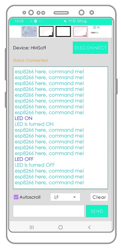
- Finally, type either "LED ON" or "LED OFF" in the Android app and press the "SEND" button.

- The ESP8266 board will receive the data, and then print a response to the Serial port. This response will be sent to the Bluetooth app, and the result can be seen on the Android app.
- Examine the output displayed on the Serial Monitor of the Arduino IDE.
Once you have gone through the steps above,. you will observe that the information displayed on the Serial Monitor of the Arduino IDE and the Android app is identical.
ESP8266 Code - Control LED with smartphone App via BLE
This ESP8266 example code uses the commands “ON” and “OFF” that are received through the Bluetooth Serial Monitor App to switch a built-in LED on or off.
You can get a closer look at the instructions by visiting the ESP8266 controls LED via Bluetooth/BLE tutorial. To get a better understanding of the instructions, check out the ESP8266 controls LED via Bluetooth/BLE tutorial. For a thorough examination of the instructions, refer to the ESP8266 controls LED via Bluetooth/BLE tutorial
ESP8266 Code - Control Servo Motor with smartphone App via BLE
- The ESP8266 code below is for the purpose of receiving an angle value. 2. This value is sent via the Bluetooth Serial Monitor App. 3. The angle value is used to control the angle of a servo motor.
You can find further information on the instructions in the tutorial titled ESP8266 controls Servo Motor via Bluetooth/BLE. For a more detailed look at the instructions, please refer to the ESP8266 controls Servo Motor via Bluetooth/BLE tutorial.
If you find the Bluetooth Serial Monitor app helpful, please show your appreciation by giving it a 5-star rating on Play Store. Your support is greatly appreciated!