ESP8266 - Button
This tutorial instructs you how to use ESP8266 with button. In detail, we will learn:
- How to connect the button to ESP8266
- How to program ESP8266 to read the state of the button
- How to program ESP8266 to detect the pressing and releasing events from button.
- How to prevent the floating input problem when using the button with ESP8266.
- How to prevent the chattering problem when using the button with ESP8266.
The button is known by other names, such as pushbutton, tactile button or momentary switch. It is a common component used in many ESP8266 projects and is easy to use. However, it can be confusing for beginners due to its mechanical, physical aspects and the ways it can be used. This tutorial makes it easier for those just starting out.
Hardware Preparation
Or you can buy the following kits:
| 1 | × | DIYables Sensor Kit (18 sensors/displays) |
Additionally, some of these links are for products from our own brand, DIYables .
Overview of Button
When working with a button, beginners commonly encounter two issues:
1. Floating input problem:.
- Symptom: The value read from the input pin does not correspond with the state of the button press.
- Cause: A pull-up or pull-down resistor is not in use with the input pin.
- Solution: Utilize a pull-up or pull-down resistor as instructed in this tutorial.
2. Chattering phenomenon:.
- Symptom: Despite being pressed once, the button is causing the ESP8266 code to detect multiple presses.
- Cause: The state of the button (or switch) is rapidly oscillating between LOW and HIGH due to mechanical and physical issues.
- Solution: The ESP8266 - Button - Debounce tutorial will explain how to utilize debounce to address this problem.
This is a factor that should only be taken into account for applications that require precise press detection.
The Button Pinout
There are various types of push buttons, which can be broadly categorized into two groups:
- PCB-mount push button (suitable for mounting on a breadboard)
- Panel-mount push button
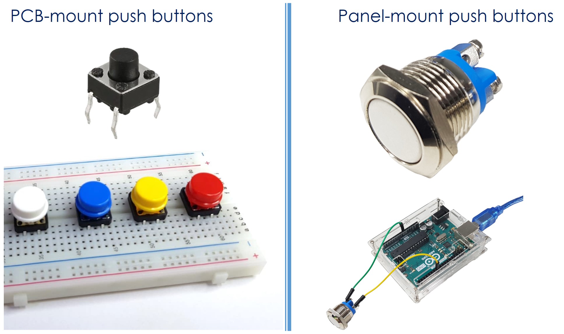
A PCB-mount button typically have four pins.
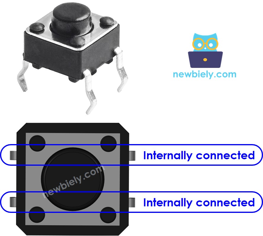
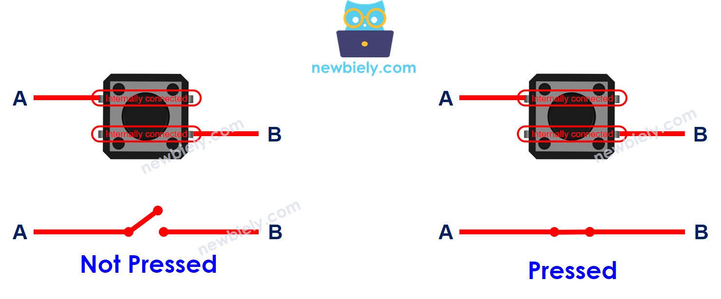
Nevertheless, these pins are connnected in pair internally. Thus, we only have to utilize two of the four pins, which are not connnected within.
There are four methods of connecting to the button, two of which are symmetrical (as seen in the image).
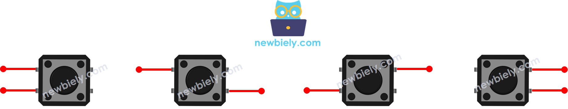
? Why does a button have four pins when we only use two of them?
⇒ To ensure that it is firmly mounted on the PCB (printed circuit board) and can withstand the pressure.
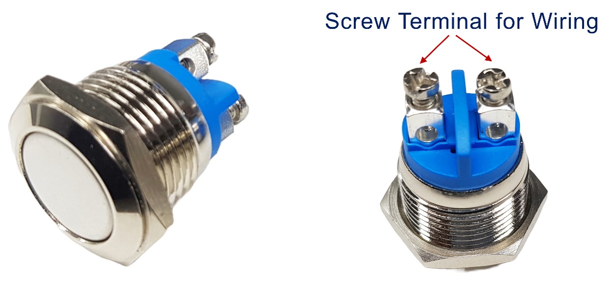
A panel-mount button usually have two pins.
The push button module includes an built-in pull-down resistor, which ensures that the output remains LOW when the button is not pressed. It has three pins:
- GND: Connect this pin to ground.
- VCC: Connect this pin to a 3.3V power supply.
- OUT: Connect this pin to a digital input on your ESP8266.
With this configuration, the module outputs LOW when the button is not pressed and outputs HIGH when the button is pressed.
How It Works
- When the button is not pressed, pin A is not connected to pin B.
- However, when the button is pressed, pin A is connected to pin B.
ESP8266 - Button
One button's pin is connected to either VCC or GND. The other pin is connected to a pin on the ESP8266. By checking the state of an ESP8266 pin configured as an input, we can determine whether a button has been pressed or not.
Button State and Pressing State
The connection between the button and ESP8266, as well as the configuration of the ESP8266's pin, will determine the relationship between the button state and the pressing state.
There are two ways to use a button with ESP8266:
- One button's pin is connected to VCC, the other is connected to an ESP8266's pin with a pull-down resistor
- When the button is pressed, the ESP8266's pin state will be HIGH. If not, the pin state will be LOW
- We can either use an internal or external resistor. The internal resistor is already built inside ESP8266, and can be set via ESP8266 code.
- When the button is pressed, the ESP8266's pin state will be LOW. If not, the pin state will be HIGH
- We can either use an internal or external resistor. The internal resistor is already built inside ESP8266, and can be set via ESP8266 code.
※ NOTE THAT:
If we do not follow the best practice, the state of the input pin will be “floating” when the button is NOT pressed. This means the state can be HIGH or LOW (unstable, unfixed), resulting in wrong detection.
- The worst practice: initializes the ESP8266 pin as an input (by using pinMode(BUTTON_PIN, INPUT)) and does NOT use any external pull-down/pull-up resistor.
- The best practice: initializes the ESP8266 pin as an internal pull-up input (by using pinMode(BUTTON_PIN, INPUT_PULLUP)). It does NOT need to use any external pull-down/pull-up resistor.
For the sake of simplicity, this tutorial utilizes the most basic approach: initializing the ESP8266 pin as an internal pull-up input without the use of an external resistor. Newcomers do not have to worry about connecting the pull-up/pull-down resistor. All they need to do is write the ESP8266 code.
Wiring Diagram
- Wiring Diagram between ESP8266 and PCB-mount button
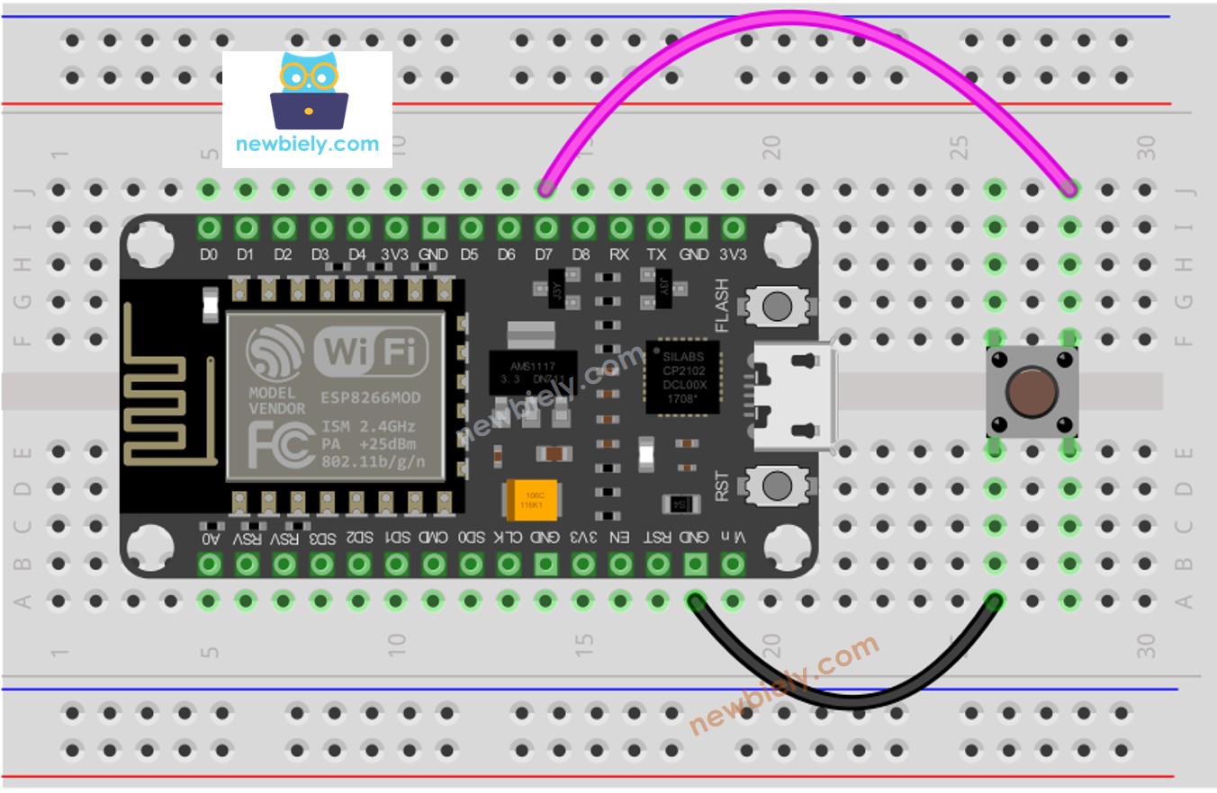
This image is created using Fritzing. Click to enlarge image
- Wiring Diagram between ESP8266 and panel-mount button
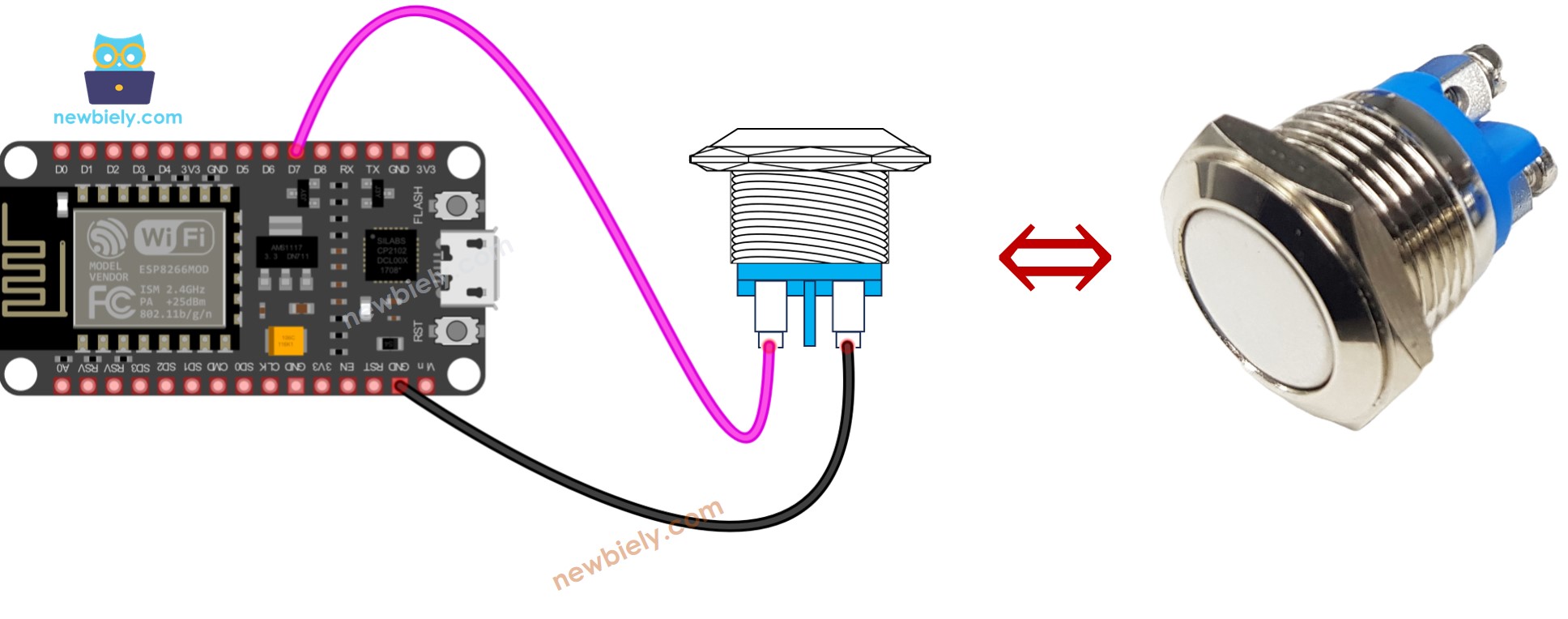
This image is created using Fritzing. Click to enlarge image
See more in ESP8266's pinout and how to supply power to the ESP8266 and other components.
ESP8266 Code
Detailed Instructions
To get started with ESP8266 on Arduino IDE, follow these steps:
- Check out the how to setup environment for ESP8266 on Arduino IDE tutorial if this is your first time using ESP8266.
- Wire the components as shown in the diagram.
- Connect the ESP8266 board to your computer using a USB cable.
- Open Arduino IDE on your computer.
- Choose the correct ESP8266 board, such as (e.g. NodeMCU 1.0 (ESP-12E Module)), and its respective COM port.
- Attach the ESP8266 to your computer with a USB cable.
- Launch the Arduino IDE, select the correct board and port.
- Copy the code below and open it in the Arduino IDE.
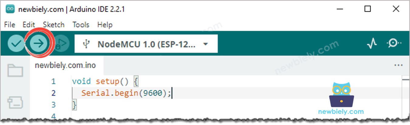
- Click the Upload button on the Arduino IDE to compile and upload the code to the ESP8266 board.
- Open the Serial Monitor.
- Press and release the button multiple times.
- Check out the result in the Serial Monitor.
1 is HIGH,. 0 is LOW.
Code Explanation
Check out the line-by-line explanation contained in the comments of the source code!
Modifying ESP8266 Code
Let's change the code so that it can detect when a press and release event occurs.
Detailed Instructions
- Wire the components as shown in the diagram.
- Connect the ESP8266 board to your computer using a USB cable.
- Open Arduino IDE on your computer.
- Choose the correct ESP8266 board, such as (e.g. NodeMCU 1.0 (ESP-12E Module)), and its respective COM port.
- Alter the code as follows:
- Click the Upload button on the Arduino IDE to compile and upload the code to the ESP8266.
- Open the Serial Monitor.
- Press the button and hold it down.
- Release the button and observe the result in the Serial Monitor.
※ NOTE THAT:
Even if you press and release the button just once, the output in the Serial Monitor may display multiple pressed and released events. This is the expected behavior of the button. This is known as the "chattering phenomenon". For more information, please refer to the ESP8266 - Button Debounce tutorial.
※ NOTE THAT:
- We have developed a library, called ezButton, to make it simpler for those just starting out, particularly when using multiple buttons. You can find out more about the ezButton library here.
- If you are using the button module, configure the pin to input mode using pinMode(BUTTON_PIN, INPUT). With this setup, the module will output LOW when the button is unpressed and HIGH when the button is pressed.
Video Tutorial
Challenge Yourself
- When the button is pressed, turn on the LED.
- When the button is not pressed, turn off the LED.
- Each time the button is pressed, switch the LED between ON and OFF.
Additional Knowledge
- At what times should we NOT use a pull-down/pull-up resistor for an input pin? 2. When should we not utilize a pull-down/pull-up resistor for an input pin?
- If the sensor has either closed or open states, a pull-up or pull-down resistor is required to make these states become LOW and HIGH. Examples of such sensors are push-button, switch, magnetic contact switch (door sensor).
- On the other hand, if the sensor has two defined voltage levels (LOW and HIGH), a pull-up or pull-down resistor is not needed. Examples of such sensors are motion sensor and touch sensor.