ESP8266 - LED
This tutorial instructs you how to use ESP8266 to control an LED. In detail, we will learn:
- How to connect the LED to ESP8266
- How to program ESP8266 to turn the LED on or off.
- How to program ESP8266 to blink the LED.
Hardware Preparation
Or you can buy the following kits:
| 1 | × | DIYables Sensor Kit (18 sensors/displays) |
Additionally, some of these links are for products from our own brand, DIYables .
Buy Note: Use the LED Module for easier wiring. It includes an integrated resistor.
Overview of LED
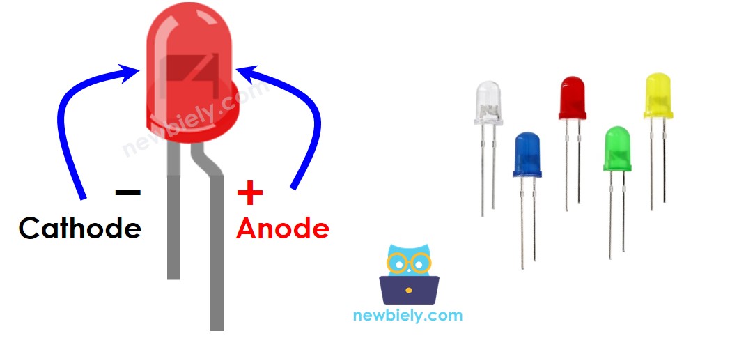
The LED Pinout
LED has two pins:
- The Cathode(-) pin: should be connected to the negative of power supply
- The Anode(+) pin: should be connected to the positive of power supply via a resistor
How It Works
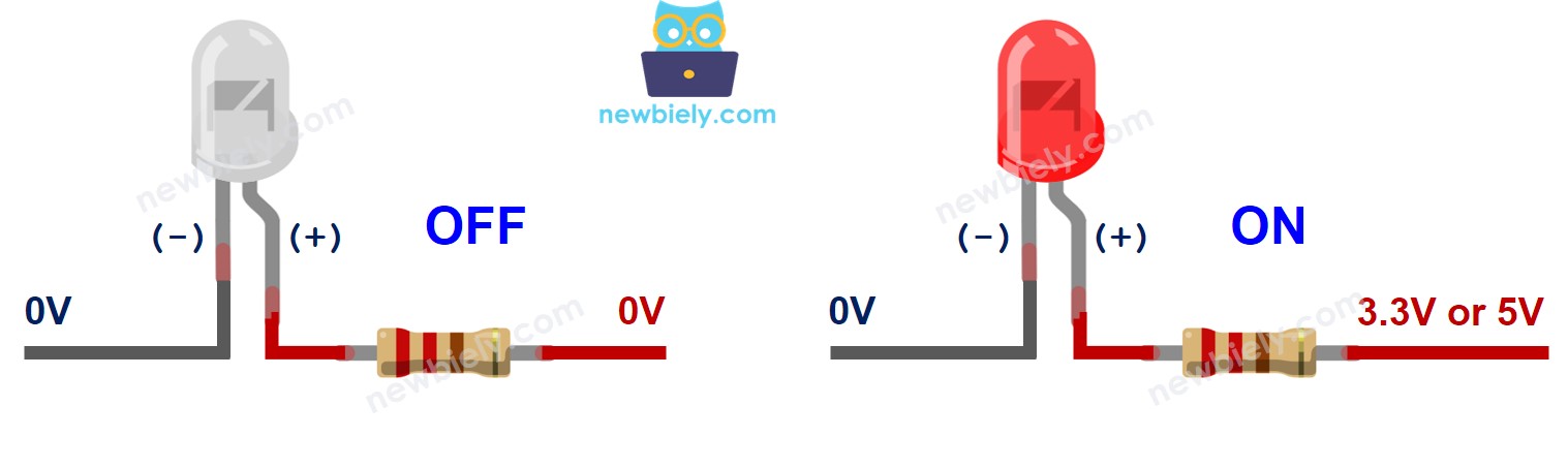
The below table shows the LED state according to how the power connects to LED's pin
| LED cathode(-) pin | LED anode(+) pin | Condition | LED state |
|---|---|---|---|
| GND | VCC | via a resistor | ON |
| GND | PWM | via a resistor | ON, variable brightness |
| GND | GND | any | OFF |
| VCC | VCC | any | OFF |
| VCC | GND | any | burned! cautious! |
As shown on the above table, by generating a PWM signal to the anode (+) of an LED, the brightness of the LED varies in accordance with the PWM value. This has been explained in detail in ESP8266 fade LED tutorial.
※ NOTE THAT:
- For most of LED, a resistor is required to protect LED from the current. There are two options to place the resistor: between the anode(+) and VCC, or between the cathode(-) and GND. The value of the resistor depends on the specification of the LED.
- Some kinds of LEDs have a built-in resistor. In this case, the resistor is not required.
ESP8266 - LED
When an ESP8266's pin is set up as a digital output, it can be programmed to have either the GND or VCC voltage.
Connect the ESP8266's pin to the anode(+) pin of the LED with a resistor. This will allow us to control the state of the LED through programming.
Wiring Diagram
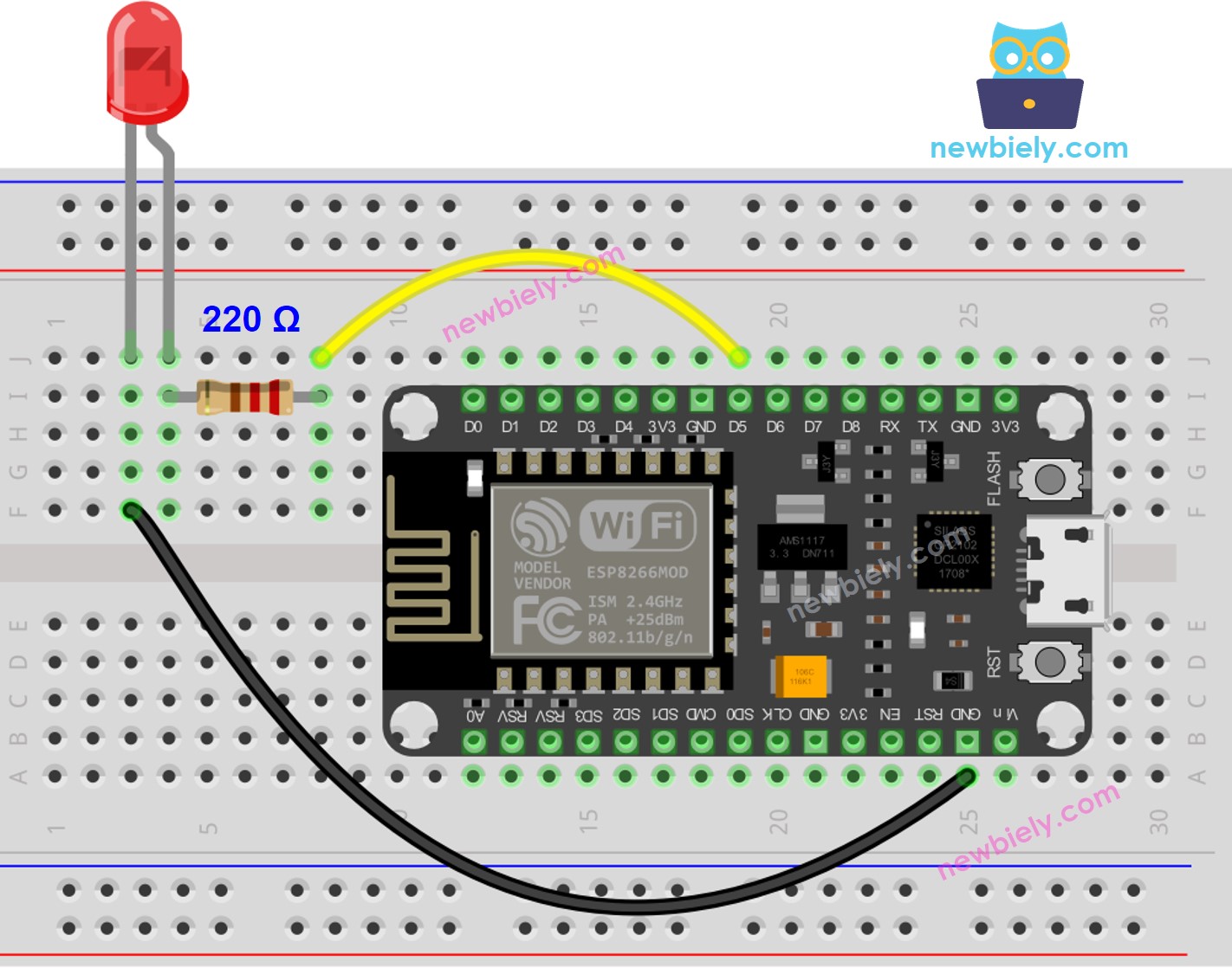
This image is created using Fritzing. Click to enlarge image
See more in ESP8266's pinout and how to supply power to the ESP8266 and other components.
How To Program
- Set the pin of an ESP8266 to digital output mode by utilizing the pinMode() function. For instance, pin GPIO9:
ESP8266 Code for controlling LED
Detailed Instructions
To get started with ESP8266 on Arduino IDE, follow these steps:
- Check out the how to setup environment for ESP8266 on Arduino IDE tutorial if this is your first time using ESP8266.
- Wire the components as shown in the diagram.
- Connect the ESP8266 board to your computer using a USB cable.
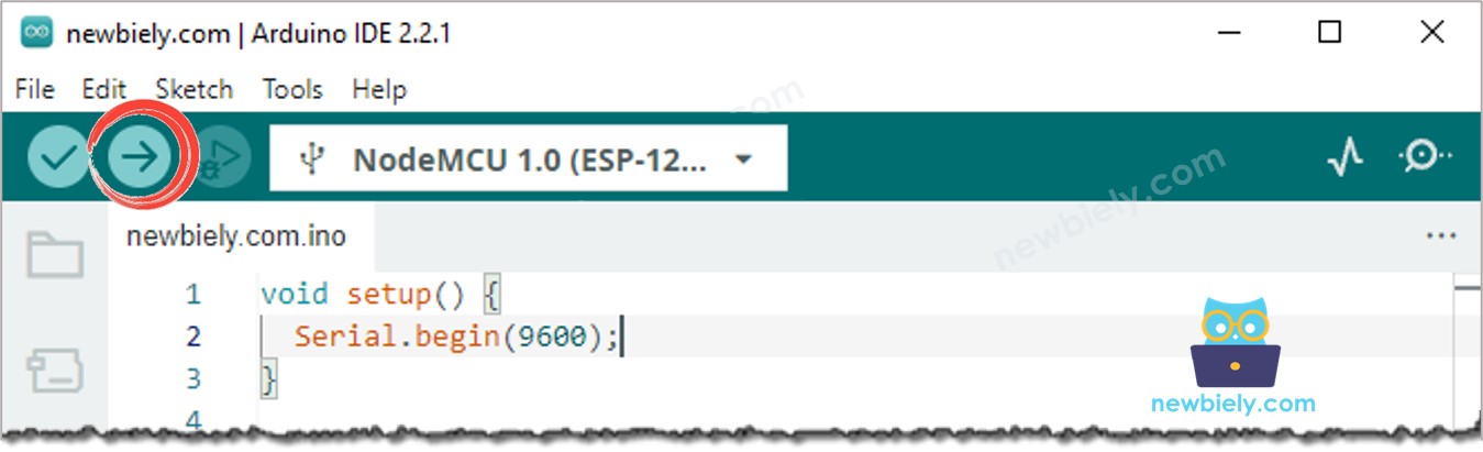
- Open Arduino IDE on your computer.
- Choose the correct ESP8266 board, such as (e.g. NodeMCU 1.0 (ESP-12E Module)), and its respective COM port.
- Click the Upload button on Arduino IDE to compile and upload the code to the ESP8266 board.
- Check out the outcome: The internal LED light switches between being ON and OFF in a regular pattern every second.
Code Explanation
Check out the line-by-line explanation contained in the comments of the source code!
※ NOTE THAT:
The code above makes use of delay(). This function prevents ESP8266 from performing other tasks during the delay period. If your project necessitates the completion of certain tasks, you should avoid blocking ESP8266 by utilizing the non-blocking method for Arduino.
Video Tutorial
Additional Knowledge
- At one time, a pin can only does a single task. If it has already been assigned to another job (e.g., digital input, analog input, PWM, UART, etc.), then it should NOT be used as a digital output to control an LED. For instance, if we use the Serial.println() function, pins GPIO1 (TX) and GPIO3 (RX) should not be used for any other purpose because they are reserved for Serial.
- This tutorial demonstrates how to use the output pin of an ESP8266 to control an LED. We can utilize this code to switch ON/OFF any apparatus, even large machines.
- For devices/machines that require a power supply greater than 5 volts and/or high-current consumption, a relay must be used between the output pin and the device/machine. Further information can be found at ESP8266 - Relay.