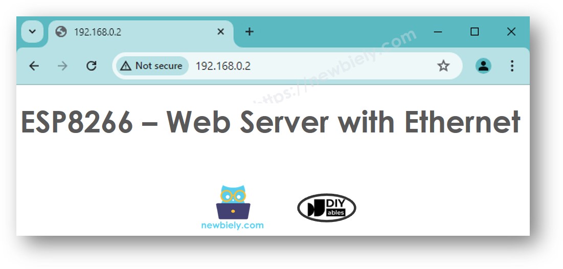
ESP8266 - Ethernet
This guide shows you how to connect the ESP8266 to the Internet or your local network using the W5500 Ethernet module. Here's what we will discuss:
- Linking ESP8266 with W5500 Ethernet Module
- Programming ESP8266 for Web Requests via Ethernet
- Creating a Basic Web Server on ESP8266 with Ethernet
Hardware Preparation
Or you can buy the following kits:
| 1 | × | DIYables Sensor Kit (30 sensors/displays) | |
| 1 | × | DIYables Sensor Kit (18 sensors/displays) |
Additionally, some of these links are for products from our own brand, DIYables .
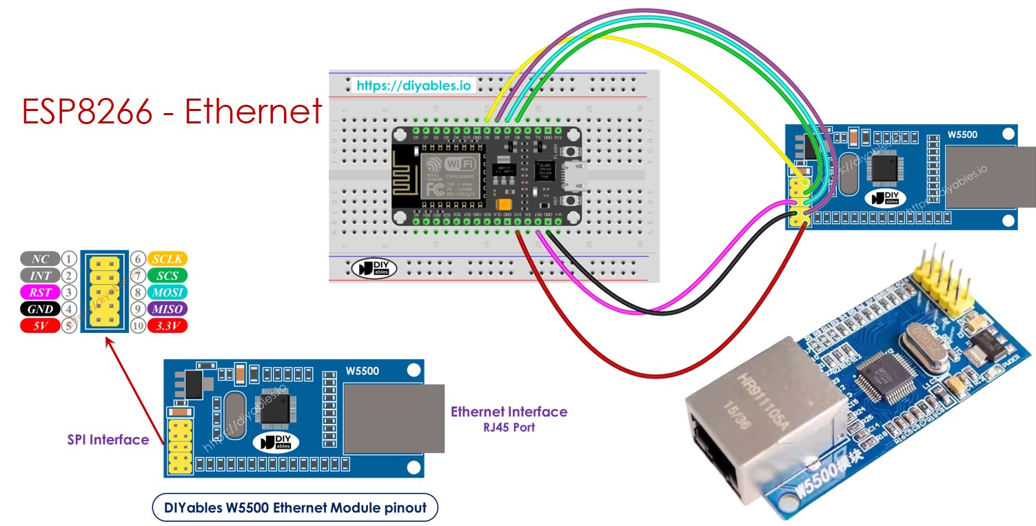
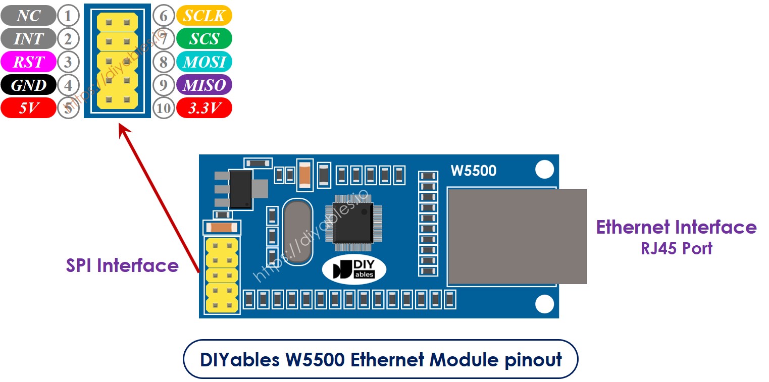
Overview of W5500 Ethernet module
The W5500 Ethernet module has two kinds of connections:
- RJ45 interface: Connect this to a network device like a router or a switch using an Ethernet cable.
- SPI interface: Connect this to an ESP8266 board using the following connections for its 10 pins:
- NC pin: Leave this pin unconnected.
- INT pin: Leave this pin unconnected.
- RST pin: Connect this to the reset (EN) pin on the ESP8266.
- GND pin: Connect this to the ground (GND) pin on the ESP8266.
- 5V pin: Do not connect this pin.
- 3.3V pin: Connect this to the 3.3V pin on the ESP8266.
- MISO pin: Connect this to the SPI MISO pin on the ESP8266.
- MOSFi pin: Connect this to the SPI MOSI pin on the ESP8266.
- SCS pin: Connect this to the SPI CS (Chip Select) pin on the ESP8266.
- SCLK pin: Connect this to the SPI SCK (Clock) pin on the Arauthenticated.
Wiring Diagram between ESP8266 and W5500 Ethernet module
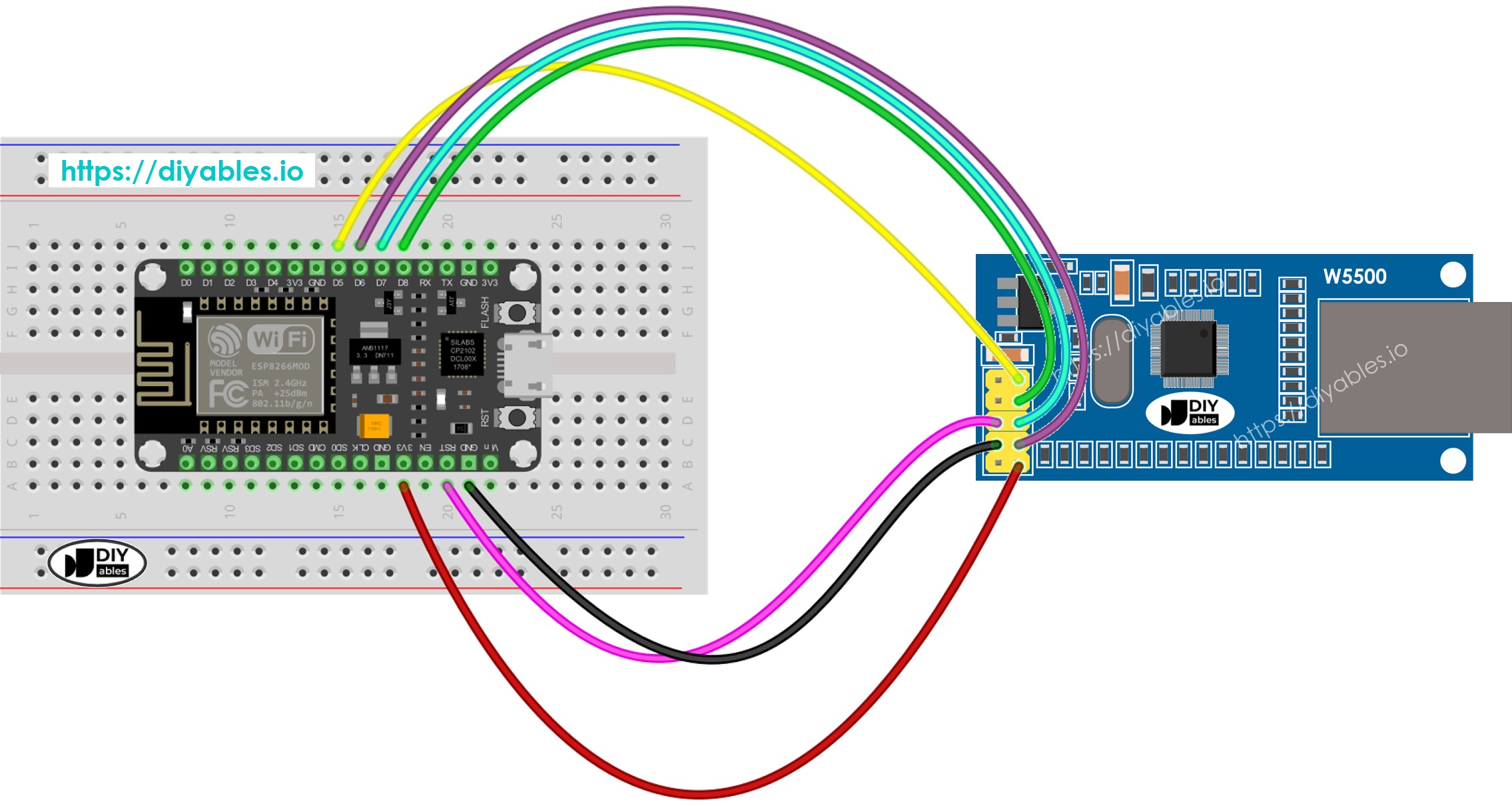
This image is created using Fritzing. Click to enlarge image
See more in ESP8266's pinout and how to supply power to the ESP8266 and other components.
ESP8266 code for Ethernet Module - Making HTTP request via Ethernet
This code works as a web client. It sends HTTP requests to the web server at http://example.com/.
Detailed Instructions
To get started with ESP8266 on Arduino IDE, follow these steps:
- Check out the how to setup environment for ESP8266 on Arduino IDE tutorial if this is your first time using ESP8266.
- Connect the Ethernet module to the ESP8266 board as shown in the wiring diagram.
- Use an Ethernet cable to connect the Ethernet module to your router or switch.
- Connect the ESP8266 board to your computer using a USB cable.
- Open Arduino IDE on your computer.
- Choose the correct ESP8266 board, such as (e.g. NodeMCU 1.0 (ESP-12E Module)), and its respective COM port.
- Click to the Libraries icon on the left bar of the Arduino IDE.
- Search Ethernet, then find the Ethernet library by Various
- Click Install button to install Ethernet library.
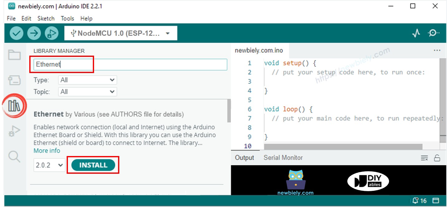
- Open the Serial Monitor in the Arduino IDE.
- Copy the code given and paste it into the Arduino IDE.
- Press the Upload button in the Arduino IDE to send the code to the ESP25.
- Check out the result on the Serial Monitor which will show the result as below.
※ NOTE THAT:
If another device on the same network has the same MAC address, it may not function properly.
ESP8266 code for Ethernet Module - Web Server
The code below transforms the ESP8266 into a web server. This server delivers a basic webpage to internet browsers.
Detailed Instructions
- Copy the above code and paste it into the Arduino IDE.
- Click the Upload button in Arduino IDE to transfer the code to the ESP8266.
- Check the results on the Serial Monitor; they will display as described.
- Copy the IP address given above and enter it into your web browser’s address bar. You will see a simple webpage displayed by the ESP8266.
