
ESP32 S3 - Sound Sensor - LED
This tutorial shows you how to use the ESP32 S3 together with a sound sensor to control an LED automatically based on detected sound. By wiring a digital sound sensor to a GPIO input and an LED to a GPIO output, you will gain a practical understanding of how to respond to real-world audio events with a visual indicator on the ESP32 S3.
What you'll build:
- A circuit connecting a sound sensor and an LED to the ESP32 S3
- A sound switch that toggles the LED state each time a sound is detected by the ESP32 S3
- A sound-activated LED system that turns the LED on for a specific period of time when sound is detected
- A foundation for building sound-triggered alarms, interactive lighting, and audio-responsive projects
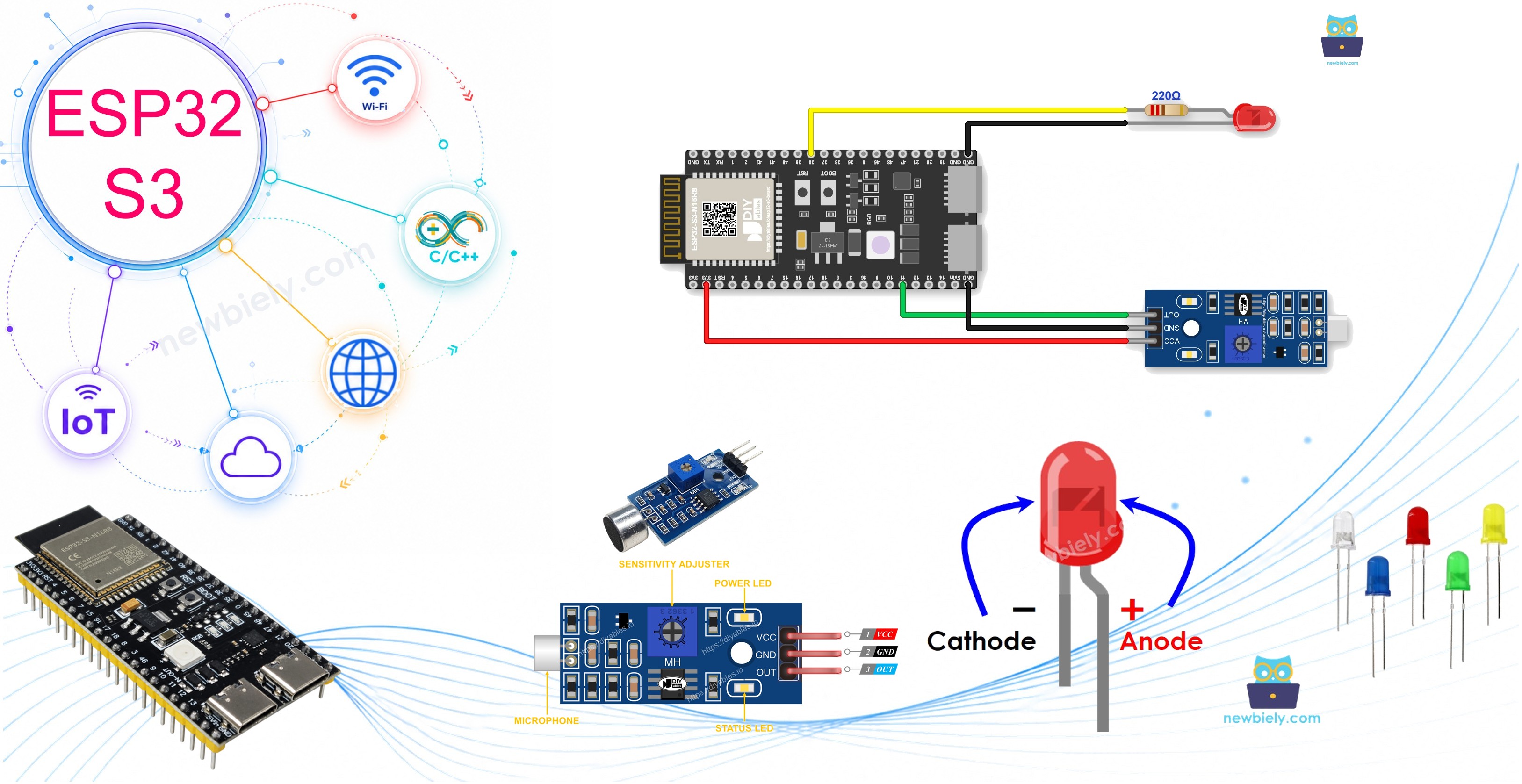
Hardware Preparation
Or you can buy the following kits:
| 1 | × | DIYables ESP32 S3 Starter Kit (ESP32 S3 included) | |
| 1 | × | DIYables Sensor Kit (18 sensors/displays) |
Additionally, some of these links are for products from our own brand, DIYables .
Buy Note: Use the LED Module for easier wiring. It includes an integrated resistor.
Overview of LED and Sound Sensor
A sound sensor and an LED are an effective pairing for building sound-responsive projects on the ESP32 S3. The sensor detects sound vibrations above a configurable threshold, outputs a digital signal on its data pin, and the ESP32 S3 reads that signal to switch the LED on or off via a digital GPIO output.
Key Specifications
We have dedicated tutorials covering each component in depth. Each tutorial contains detailed information and step-by-step instructions about hardware pinout, working principle, wiring connection to the ESP32 S3, and Arduino code. Learn more about them at the following links:
Wiring Diagram
Connect the sound sensor and LED to your ESP32 S3 by following the diagram below. Double-check all connections before applying power, paying particular attention to the LED polarity and the 220 ohm current-limiting resistor placement.
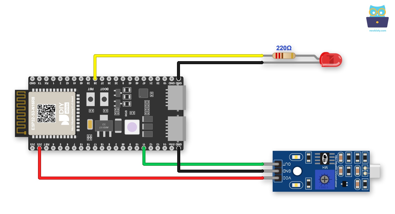
This image is created using Fritzing. Click to enlarge image
You can also put the LED and its 220 ohm resistor on a breadboard, as shown below:
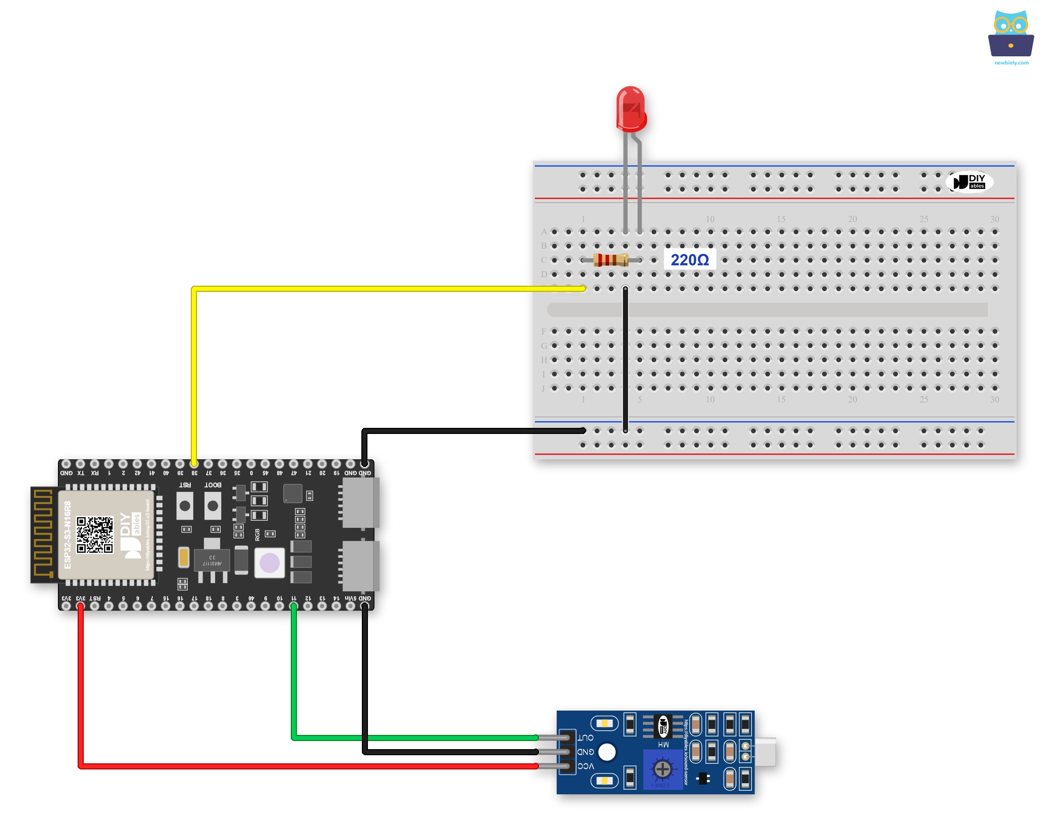
This image is created using Fritzing. Click to enlarge image
Safety Notes
Always include the 220 ohm current-limiting resistor in series with the LED to avoid drawing excessive current through the ESP32 S3 GPIO pin, which can permanently damage the microcontroller. The sound sensor module typically operates at 3.3V to 5V; use the 3.3V output pin available on the ESP32 S3 board for powering the sensor to keep all signal levels compatible with the ESP32 S3's GPIO inputs.
ESP32 S3 Code - Sound Switch Toggles LED
The following code toggles the state of the LED each time the sound sensor detects a sound on the ESP32 S3. Each new sound detection event flips the LED from off to on, or from on to off, creating a simple clap-switch or knock-switch effect.
Detailed Instructions
- New to ESP32 S3? Complete our Getting Started with ESP32 S3 guide first.
- Wire the components following the wiring diagram shown above.
- Connect the ESP32 S3 board to your PC using a USB Type-C cable.
- Open Arduino IDE on your PC.
- Select the correct ESP32 S3 board and COM port from the Tools menu.
- Copy the above code and paste it into Arduino IDE.
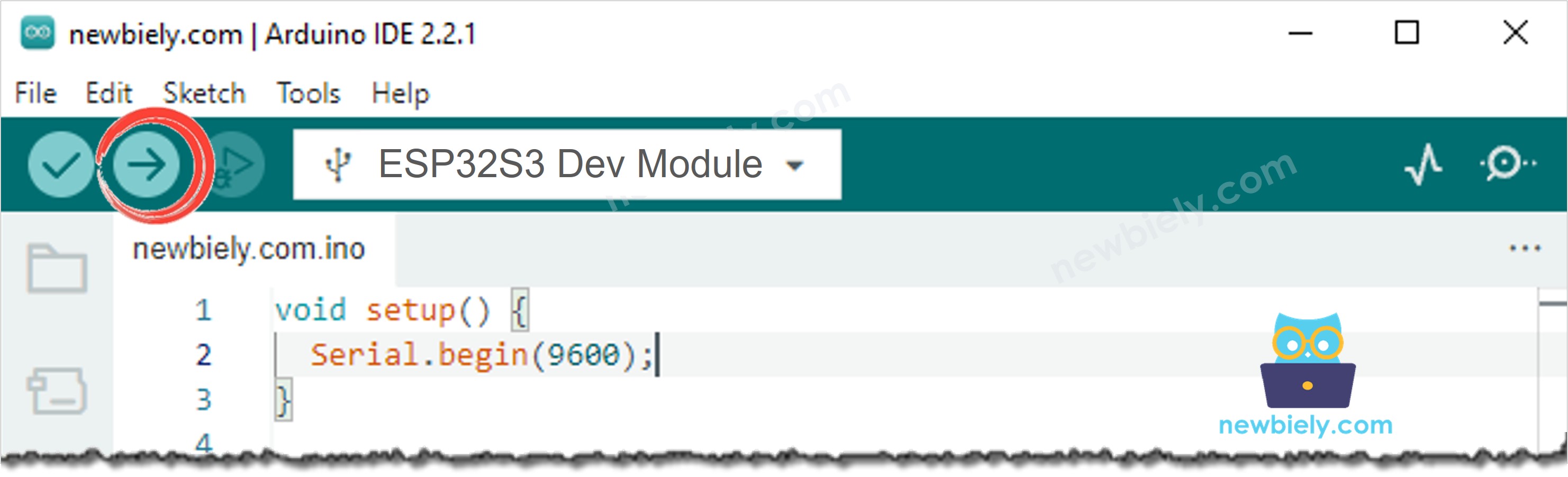
- Click the Upload button to compile and upload the code to the ESP32 S3.
- Clap your hand in front of the sound sensor.
- Observe the LED toggle its state each time a clap is detected.
- Pro Tip: Adjust the onboard sensitivity trimmer potentiometer on the sound sensor module to fine-tune the detection threshold so it responds reliably to claps or knocks without triggering on ambient background noise.
ESP32 S3 Code - Sound-Activated LED for a Period of Time
The following code turns the LED on for a defined period of time when the sound sensor detects a sound on the ESP32 S3, then turns the LED off automatically once that time has elapsed.
Please take note that the previous code utilises the delay() function, which is straightforward to understand. However, when additional code is added, the delay() function can cause blocking issues during the delay period. To overcome this, the following code implements a non-blocking approach by utilising the ezLED library. The ezLED library, working behind the scenes, utilises the millis() function instead of delay to prevent blocking.
Detailed Instructions
- New to ESP32 S3? Complete our Getting Started with ESP32 S3 guide first.
- Wire the components following the wiring diagram shown above.
- Connect the ESP32 S3 board to your PC using a USB Type-C cable.
- Open Arduino IDE on your PC.
- Select the correct ESP32 S3 board and COM port from the Tools menu.
- Click the Libraries icon on the left bar of Arduino IDE.
- Search "ezLED", then find the LED library by ArduinoGetStarted.
- Click Install to install the ezLED library.
- Search for ezLED created by ArduinoGetStarted.com and click the Install button.
- Copy the above code and paste it into Arduino IDE.
- Click the Upload button to compile and upload the code to the ESP32 S3.
- Clap your hand in front of the sound sensor.
- Observe the LED turn on for the specified time period, then turn off automatically.
- Pro Tip: Adjust the LED_ON_TIME constant in the code to change how long the LED stays on after each detected sound; for a clap-light effect, a value around 5000 milliseconds (5 seconds) works well as a starting point.
Serial Monitor Output
The following Serial Monitor output shows the ESP32 S3 reading sound data from the sensor in real time. Each line displays the current sound detection state and the corresponding LED state triggered by the sensor output.
Application and Project Ideas
Once you can trigger an LED from a sound sensor on the ESP32 S3, you can extend this pattern to a wide range of sound-activated and audio-responsive projects.
- Clap-activated light switch: Use the toggle sketch to turn a relay-controlled room light on or off with a single clap, creating a hands-free lighting solution.
- Sound-triggered alarm: Replace the LED with a piezo buzzer or relay-connected siren to sound an alert whenever an unexpected noise is detected in a monitored area.
- Baby monitor indicator: Turn on a bedside LED strip via a relay whenever the sound sensor detects a baby crying, providing a silent visual alert for caregivers in another room.
- Tutorial noise meter: Log each sound detection event with a timestamp to an SD card to analyse noisy periods in a tutorial environment over time.
- Interactive art installation: Use the sound-activated LED sketch as a base to drive addressable LED strips that react to music or audience clapping in real time.
- Security perimeter alert: Detect footsteps or door knocks at a monitored entry point and send an email or MQTT notification over the ESP32 S3 Wi-Fi connection.
Video Tutorial
Watch the step-by-step video walkthrough for this ESP32 S3 project below.
Challenge Yourself
Now that you can control an LED with a sound sensor on the ESP32 S3, try these progressively challenging extensions to deepen your understanding and build more capable sound-detection systems.
- Beginner: Modify the toggle sketch to print a message to the Serial Monitor each time the LED state changes, showing both the new LED state and a running count of how many sound events have occurred.
- Beginner: Add a second LED wired to a different GPIO pin and make one LED indicate "sound detected" while the other indicates "no sound", providing a two-colour status display.
- Intermediate: Add a push button that allows the user to enable or disable sound detection at runtime, with the LED giving a brief double-blink to confirm the mode has changed.
- Intermediate: Connect an I2C OLED display to the ESP32 S3 and show a live counter of sound detection events alongside the current LED state, updating the display each time a new sound is detected.
- Advanced: Send an MQTT message or email notification over the ESP32 S3 Wi-Fi connection whenever a sound is detected, enabling remote monitoring of a sound sensor deployed in another room or building.
- Advanced: Implement a pattern-recognition feature that counts rapid successive sound events (e.g. two claps within one second) and maps different clap patterns to different LED behaviours or relay outputs.