
ESP32 S3 - NTC Thermistor Temperature Sensor
A freezer door that stays open a crack overnight can spoil a whole drawer of food before anyone sees it. A small steel probe on a thin cable can catch that early. The DIYables 10K NTC thermistor probe is waterproof, reads from -20°C up to 105°C, and costs very little, and in this guide your ESP32 S3 reads it on GPIO1 and prints the temperature in Celsius and Fahrenheit.
What you'll build in this tutorial:
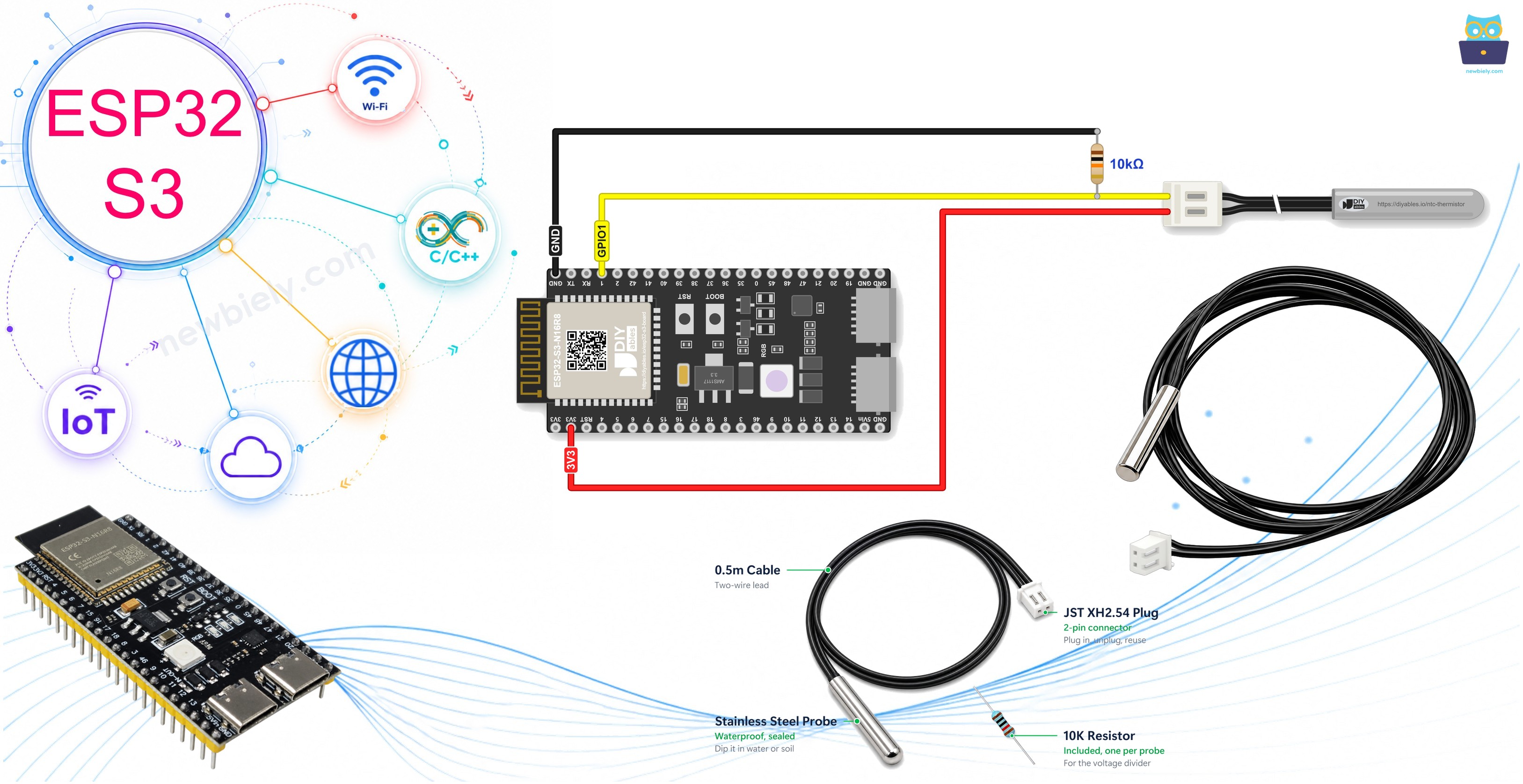
- A close look at the probe: the steel tip, the two wires without polarity, the white 2-pin plug, and the 10K resistor that comes in the kit
- A voltage divider on just three pins of the ESP32 S3: 3V3, GPIO1 and GND
- A sketch that averages calibrated millivolt readings, works out the thermistor resistance and turns it into degrees with the B formula
- A cold test with ice and salt that takes the reading below 0°C
Hardware Preparation
Or you can buy the following kits:
| 1 | × | DIYables ESP32 S3 Starter Kit (ESP32 S3 included) | |
| 1 | × | DIYables Sensor Kit (18 sensors/displays) |
Additionally, some of these links are for products from our own brand, DIYables .
Overview of NTC Thermistor Temperature Sensor

Unlike most sensor modules, this one has no board, no chip and no pin header. At the very end of the steel tip sits one tiny part, a thermistor: a resistor whose value changes a lot with temperature. The ESP32 S3 measures that resistance and turns it into degrees. Because the tip is sealed, you can drop it into water, push it into soil, or lay it on a freezer shelf, while the ESP32 S3 stays dry outside.
Key Specifications
The thermistor is 10kΩ at 25°C with a 1% tolerance, and its B value is 3950. It works from -20°C to 105°C. The stainless-steel tip is 5mm wide and 25mm long with a round end, and a black two-wire cable of 0.5m runs from it to a white JST XH2.54 2-pin plug. The insulation is more than 100MΩ. DIYables sells the probes in a set of five, and each probe comes with its own 10K resistor, so you do not have to buy one.
NTC Thermistor Pinout
The plug has two openings, and the pin of a male jumper wire pushes straight into each one. Neither opening has a label, and you do not need one:
- Probe wire A — to the 3V3 pin of the ESP32 S3
- Probe wire B — to GPIO1, where one leg of the 10K resistor also joins; the other resistor leg goes to GND
It does not matter which wire you call A. Like any resistor, the thermistor works the same way in both directions, so swapping the two wires gives the same reading.
How It Measures Temperature
NTC means Negative Temperature Coefficient. When the tip gets colder, its resistance goes up, and when it gets warmer, its resistance goes down. An ADC measures voltage, not resistance. So the thermistor and the 10K resistor sit in a row between 3V3 and GND, and GPIO1 measures the voltage at the point where they meet. A cold tip has a high resistance and leaves only a small part of the 3.3V for GPIO1. A hot tip does the opposite. Some points of the curve:
| Probe temperature | Thermistor resistance | Voltage on GPIO1 |
|---|---|---|
| -10°C | about 58.2kΩ | 0.48V |
| 0°C | about 33.6kΩ | 0.76V |
| 25°C | 10.0kΩ | 1.65V |
| 45°C | about 4.35kΩ | 2.30V |
| 85°C | about 1.09kΩ | 2.98V |
From the voltage, the sketch finds the resistance R. Then it uses the B-parameter (beta) equation:
1/T = 1/T0 + (1/B) × ln(R/R0)
Here T0 is 298.15K (25°C), R0 is 10000Ω and B is 3950. The answer T is in Kelvin, so the code takes away 273.15 to get °C. Many thermistor guides use the Steinhart-Hart equation instead. It has three constants and is a little more exact, but with this probe the B equation does the job. In practice, readings close to room temperature land within roughly 1°C of the truth; the 10K resistor and the ESP32 S3 ADC set the rest of the error.
Only need a temperature and want no math at all? The waterproof DS18B20 probe sends a ready digital value; see ESP32 S3 - Temperature Sensor. For an oven or a grill, which go far above 105°C, a thermocouple with a MAX6675 module is the right tool.
Wiring Diagram
Apart from the probe, the only part is the 10K resistor from the kit, and the ESP32 S3 gives three pins: 3V3, GPIO1 and GND. The resistor bridges the GPIO1 wire and the GND wire; a small breadboard makes this joint easy, or you can twist each resistor leg around the bare end of its wire and solder it. Why GPIO1? On the screw terminal block below, the top row starts with GND, TX, RX, 1. GPIO1 is only three terminals away from a GND terminal, so the 10K resistor can be screwed straight into both.
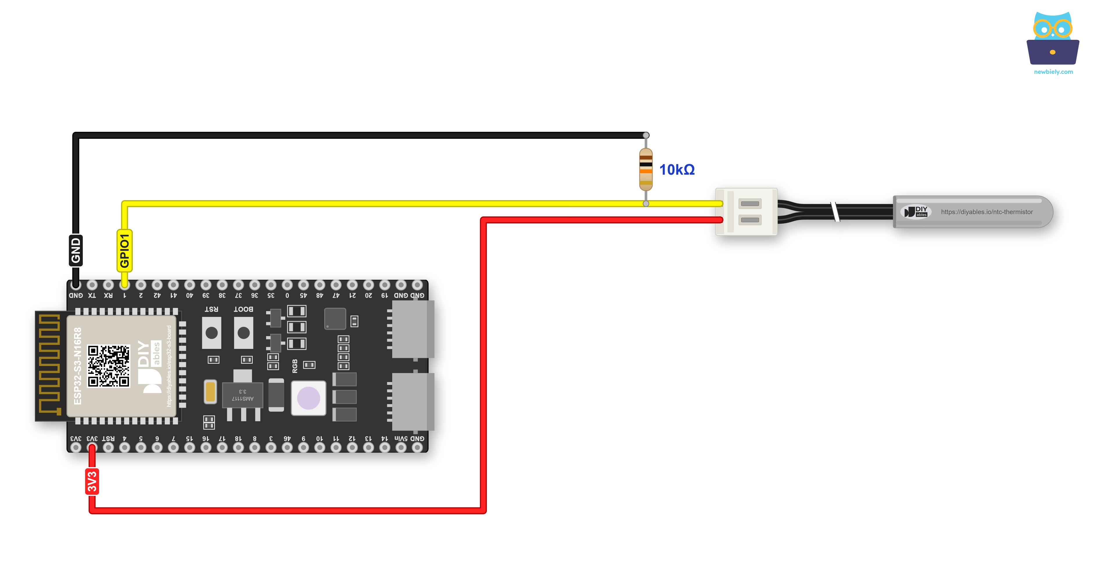
This image is created using Fritzing. Click to enlarge image
| Thermistor Circuit | ESP32 S3 Pin |
|---|---|
| Probe wire A | 3V3 |
| Probe wire B | GPIO1 (ADC1) |
| 10K resistor, one end | GPIO1 (ADC1) |
| 10K resistor, other end | GND |
Jumper wires are good for a quick test, but not for a final build. You can plug the ESP32 S3 into a Screw Terminal Block for ESP32 S3 and connect the wires to its screw terminals. Here is the same circuit wired through the screw terminal board:
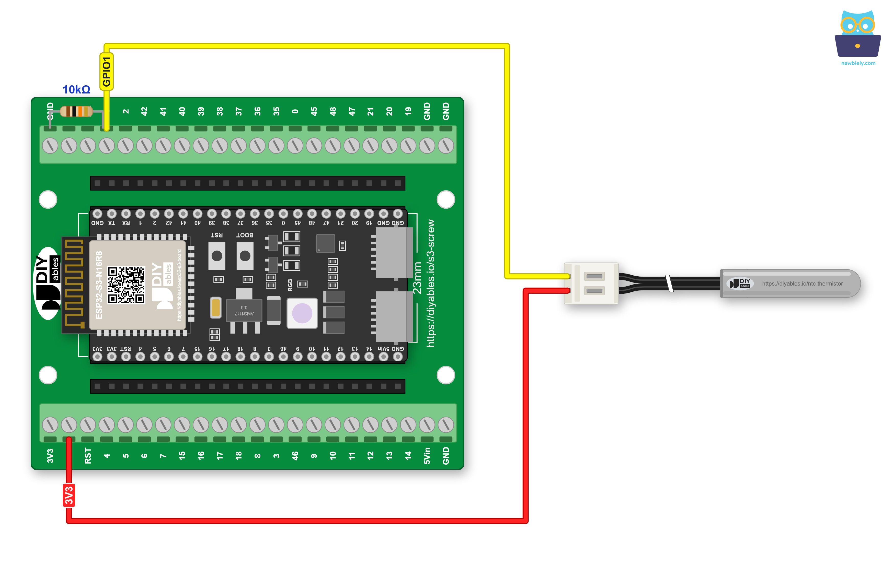
This image is created using Fritzing. Click to enlarge image
On this board the 10K resistor sits in the GND terminal and the GPIO1 terminal, and the probe wire shares the GPIO1 terminal with it, so you do not need a GND wire.
Or plug the ESP32 S3 into a GPIO Breakout Board for ESP32 S3. The same wiring then looks like this:
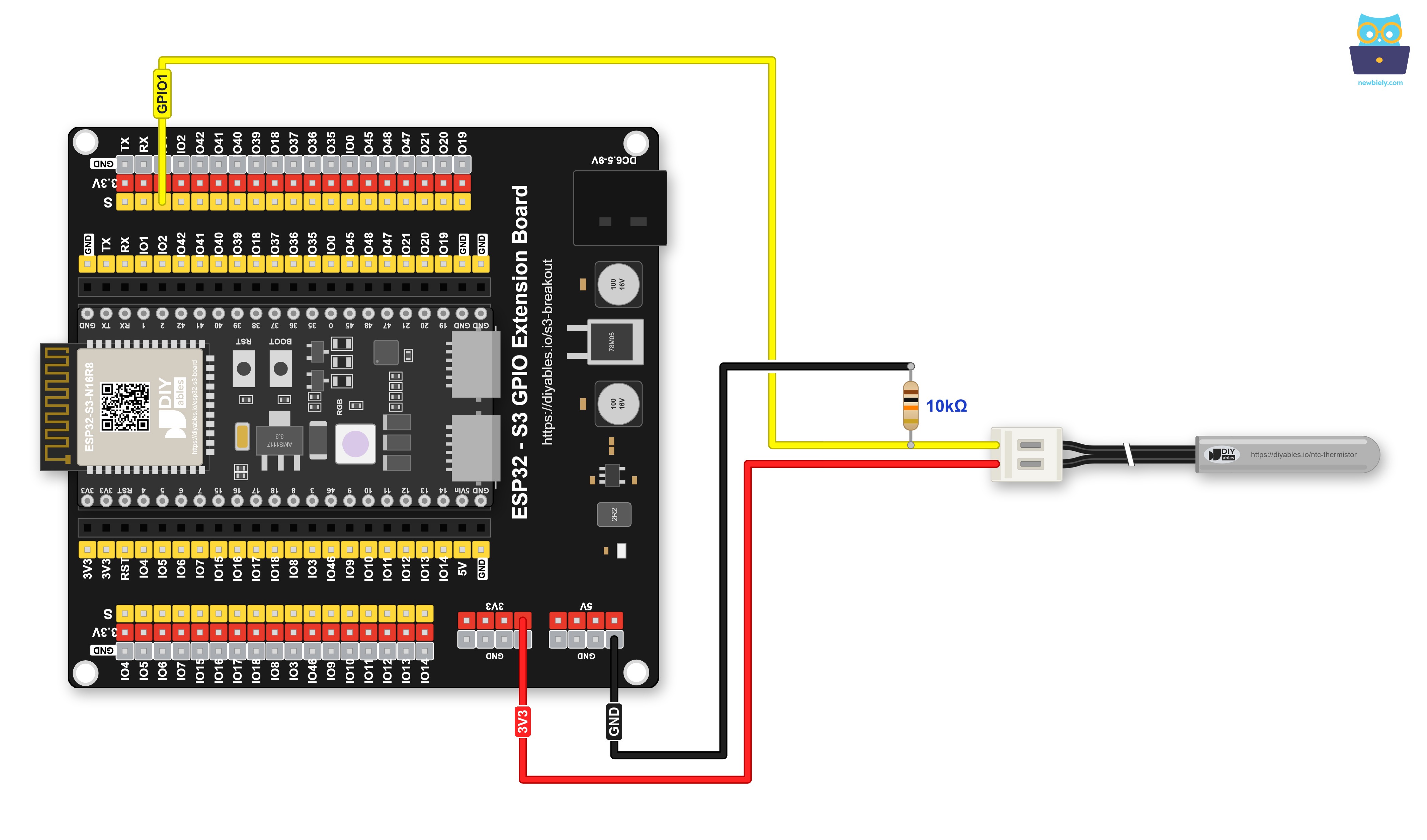
This image is created using Fritzing. Click to enlarge image
Safety Notes
Give the probe its power from 3V3 and never from 5V. The warmer the tip, the closer GPIO1 gets to the supply voltage, so with 5V a hot probe would push the pin over the 3.3V it can take. 3V3 is also the value the sketch counts on, because it uses 3300 millivolts as the top of the divider. GPIO1 belongs to ADC1, which keeps reading correctly after you turn on WiFi, while the ADC2 pins do not; that leaves room to send the temperature to a phone later without moving a wire. Last, the seal ends at the steel tip. In the ice test below, or in a fish tank, hold the white plug, the jumper wires and the resistor junction well above the water, where they stay dry.
How To Program For NTC Thermistor
No library is needed. In setup(), analogSetAttenuation(ADC_11db) lets GPIO1 measure up to about 3.1V. In loop(), the sketch takes ten analogReadMilliVolts() readings and averages them; this function uses the calibration that was stored in the chip at the factory, which is more accurate than dividing analogRead() by 4095, mostly near the low and high ends of the ESP32 S3 ADC. From the average, the resistance is 10000 × (3300 − mV) / mV, the B equation turns it into Kelvin, and two short lines give °C and °F. When the voltage is almost 0V or at the very top of the range, the sketch prints a wiring hint instead of a strange number.
ESP32 S3 Code - NTC Thermistor Temperature Sensor
Every second, this sketch prints the voltage on GPIO1, the thermistor resistance in kΩ, and the temperature in both units.
Detailed Instructions
- New to ESP32 S3? Complete our Getting Started with ESP32 S3 guide first.
- Wire the probe and the 10K resistor as shown in the table. Check twice that probe wire A sits on 3V3 and not on 5V.
- Connect the ESP32 S3 to your computer with the Type-C cable.
- In the Arduino IDE, choose ESP32S3 Dev Module under Tools > Board and the right port under Tools > Port.
- Paste the code into a new sketch and click Upload.
- Open the Serial Monitor at 9600 baud. Let a few lines go by while the probe lies on the desk.
- Fill a bowl with crushed ice, stir in two spoons of salt and a little water, then push the steel tip into the middle of it.
- Pro Tip: Salty ice is good to see the reading go below zero, but it is not a fixed point. To check the accuracy, use plain ice water without salt: after a minute, the probe should show close to 0°C. If it is always off by the same small amount, add or subtract that amount from celsius in the code.
The first three lines show a warm room at about 26°C. Then the tip goes into the bowl. The voltage drops, and the resistance climbs from about 9kΩ to more than 50kΩ, the NTC behavior from the table above. Salt makes ice melt at a lower temperature, so the mix gets colder than plain ice water and the probe passes 0°C after a few seconds. The last lines change only a little: the steel tip has reached the temperature of the bowl. Always wait for such steady lines before you trust a value.
If you see "GPIO1 reads about 0 V", the plug is loose or wire A is not on 3V3. If you see "GPIO1 is at the top of its range", the resistor does not reach GND, or the two probe wires touch.
Application and Project Ideas
A sealed probe that reads below zero and up to 105°C fits many ESP32 S3 projects at home.
- Freezer alarm: Sound a buzzer, or send a message over WiFi, when the freezer stays above -12°C for ten minutes.
- Aquarium heater check: Leave the tip in the tank and warn when the water leaves the 24°C to 28°C range.
- Fermentation logger: Write the temperature of beer, wine or yogurt to a web page every minute while it ferments.
- Hot water pipe monitor: Tape the tip to the pipe from a water heater to see when it runs and for how long.
- Battery pack guard: Tape the probe to a battery pack and switch the charger off with a relay when the pack gets too warm.
Challenge Yourself
- Beginner: Turn on an LED on GPIO4 whenever the temperature goes below 0°C.
- Intermediate: Keep the lowest and the highest temperature since power-up, and print them after every tenth reading.
- Advanced: Add a second probe and 10K resistor on GPIO7, which is also an ADC1 pin, and print both temperatures on one line, for example the fridge and the freezer.
Video Tutorial
A video for this ESP32 S3 thermistor lesson will be added here.