
ESP32 S3 - Slide Switch
The BOOT and RST keys on your ESP32 S3 both pop back up the moment you lift your finger. Some inputs must do the opposite and remember a choice, such as "send data to the cloud" or "stay offline", until a person changes it. That is where the DIYables Mini Slide Switch SS12D10 comes in, and this guide shows the ESP32 S3 reading it on GPIO21.
What you'll build in this tutorial:
- How the three unmarked legs of the SS12D10 work, and which one is COM
- A resistor-free circuit with three wires: GND on pin 1, GPIO21 on COM, 3V3 on pin 3
- A sketch that prints the starting position, then exactly one line per move, filtered by a 50 ms second look
- A 2-wire version that uses the internal pull-up of the ESP32 S3, and why its ON/OFF logic is reversed
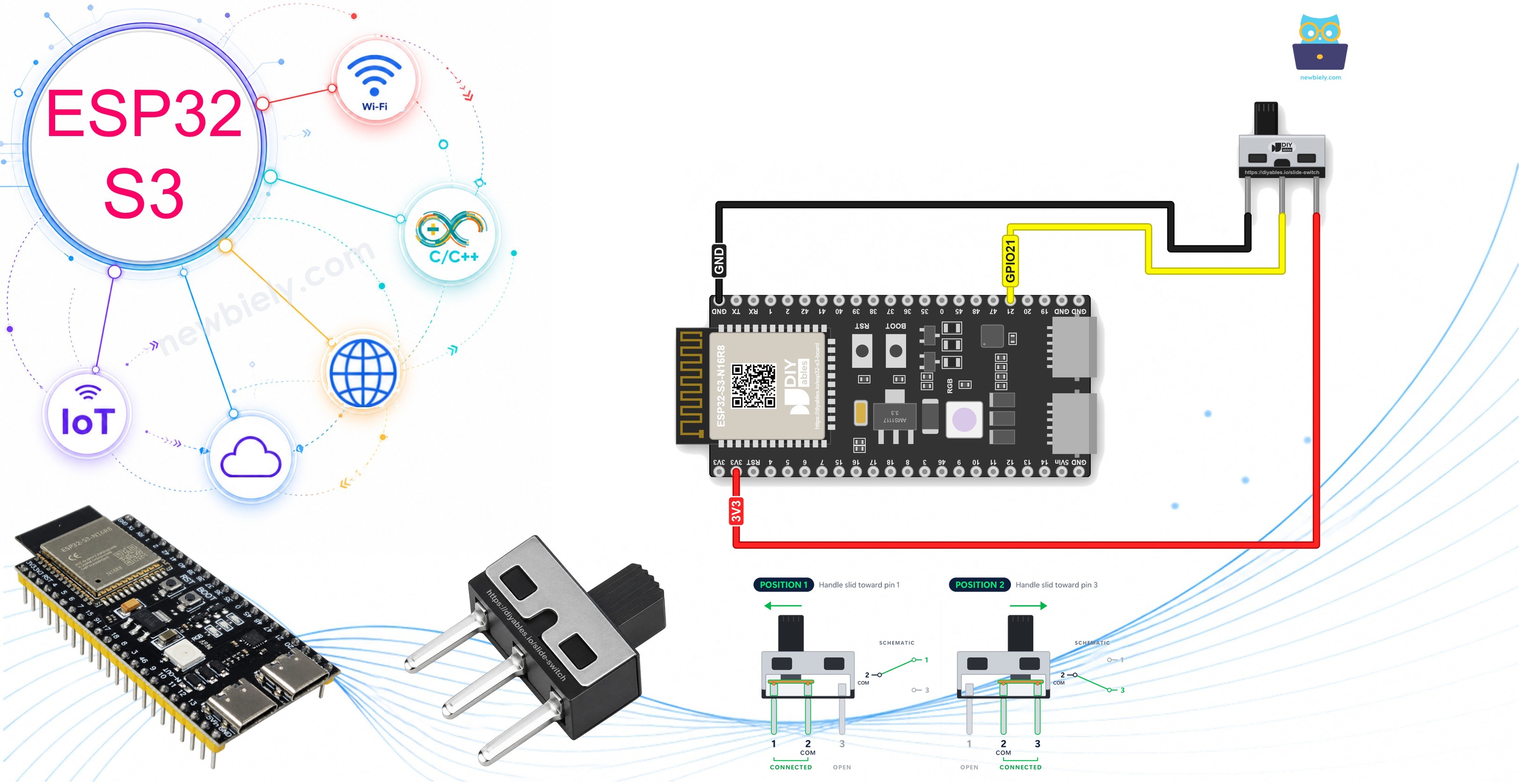
Hardware Preparation
Or you can buy the following kits:
| 1 | × | DIYables ESP32 S3 Starter Kit (ESP32 S3 included) | |
| 1 | × | DIYables Sensor Kit (18 sensors/displays) |
Additionally, some of these links are for products from our own brand, DIYables .
Overview of Slide Switch
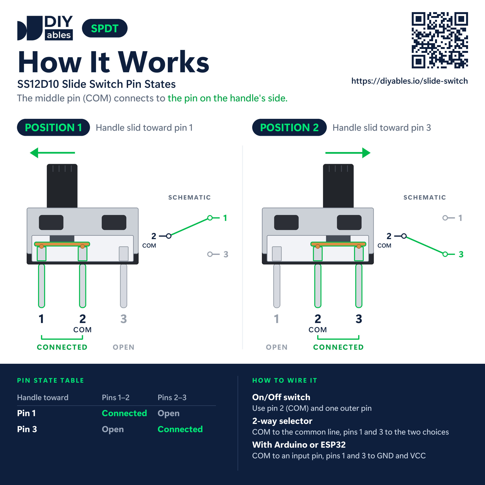
Put simply, the SS12D10 is a tiny two-way path selector. A plastic handle rides on top of a small metal case, and three legs come out underneath in a single line. Move the handle to either end, and it waits there. Only your next push moves it. Such a part is named a latching switch. A push button cannot do this, because a spring always returns it to its rest position. Its contact layout is known as SPDT (single pole, double throw), sometimes written as 1P2T.
Key Specifications
DIYables lists the switch as SPDT (1P2T) with 2 positions and 3 pins on a 4.7mm pitch. The terminals are 6.9mm long, the handle is 5mm, and the vertical through-hole body measures about 12.8 x 6.7 x 18.2mm. The silver-plated brass contacts are rated AC 125V 2A and are good for more than 100,000 switching cycles, and the part works from -25°C to 80°C. Do not read too much into 125V 2A: that is just the limit of the contacts. Here they pass just a tiny signal current.
Slide Switch Pinout
The legs carry no labels, so you tell them apart by position, counting from one end:
- Pin 1 — an end leg; in this guide it always goes to GND
- Pin 2 (COM) — the center leg, used in both positions; it carries the result to GPIO21
- Pin 3 — the other end leg; it is wired to 3V3 for the 3-wire build and left empty for the 2-wire build
Under the handle, a little metal bridge always rests on COM. Its other end lands on whichever outer leg the handle is closer to. Slide toward pin 1, and pins 1 and 2 are joined while pin 3 is open. Slide toward pin 3, and pins 2 and 3 are joined while pin 1 is open.
Which switch fits your project? A slide switch is small and sits well inside a case. For a big rocker that a finger can find on a front panel, read ESP32 S3 - Switch. For a key that springs back, see ESP32 S3 - Button Module. And when one setting is not enough, a DIP switch puts several tiny slide switches in one block.
Wiring Diagram
This circuit needs no resistor at all. With pin 1 tied to GND and pin 3 tied to 3.3V, COM always hands GPIO21 a clear LOW or HIGH, so the input never floats.
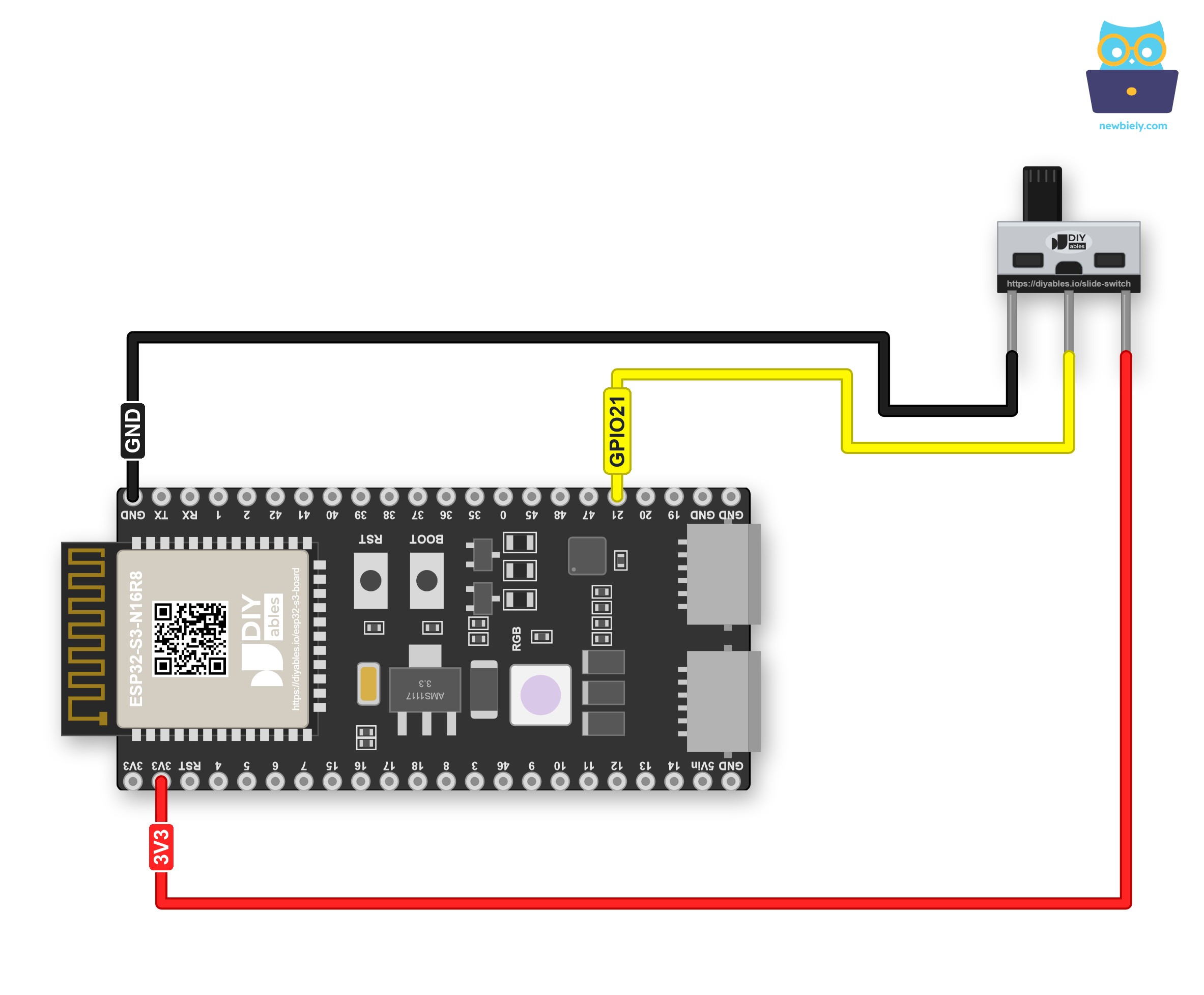
This image is created using Fritzing. Click to enlarge image
| Slide Switch Pin | ESP32 S3 Pin |
|---|---|
| Pin 1 | GND |
| Pin 2 (COM) | GPIO21 |
| Pin 3 | 3V3 |
Do you want the wiring to stay in place? Try a Screw Terminal Block for ESP32 S3: the ESP32 S3 sits on it, and each pin gets its own screw terminal. Below is the wiring diagram with the screw terminal board.
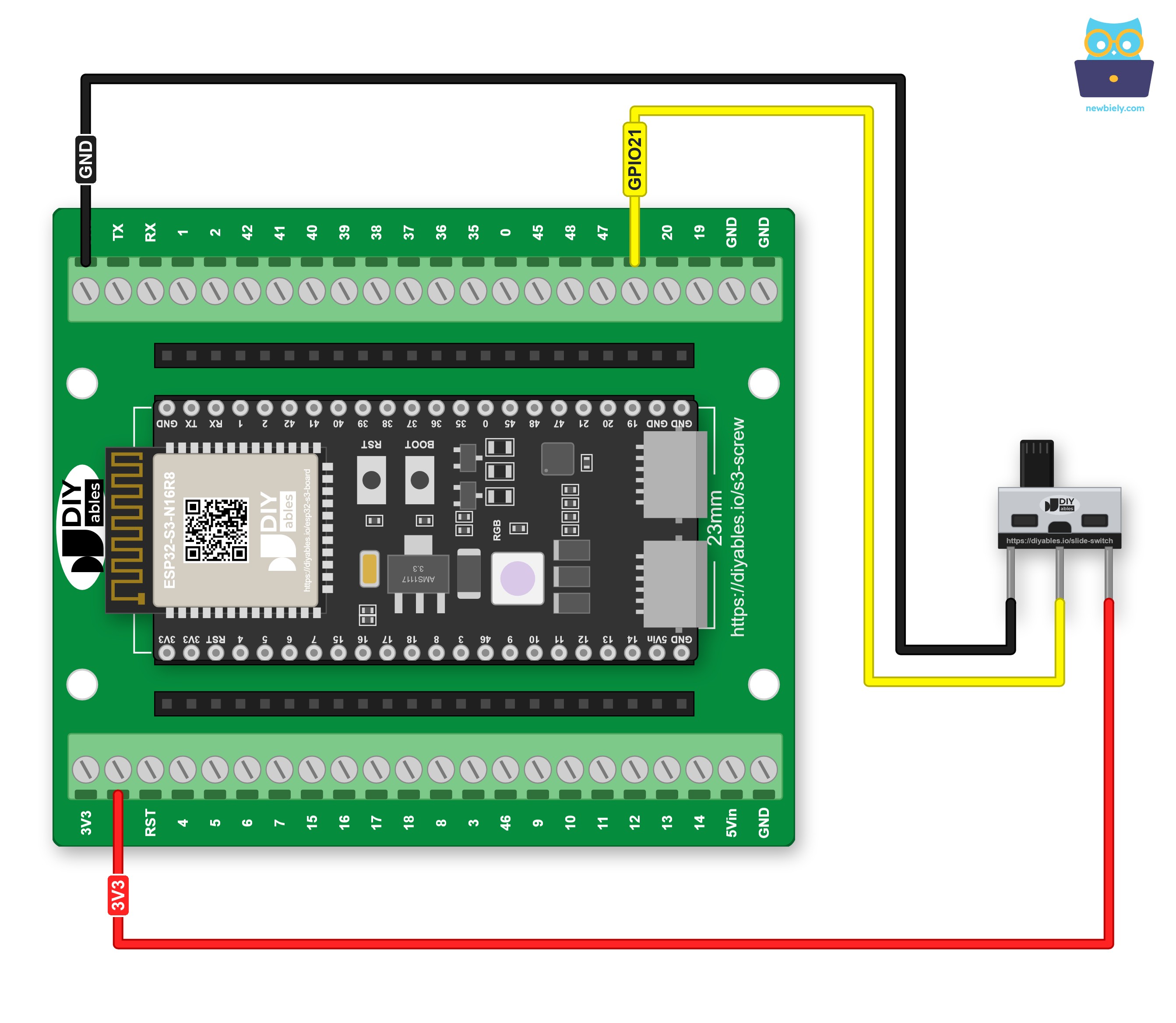
This image is created using Fritzing. Click to enlarge image
Another choice is a GPIO Breakout Board for ESP32 S3. Each GPIO has a signal pin with 3.3V and GND pins next to it, as shown below:
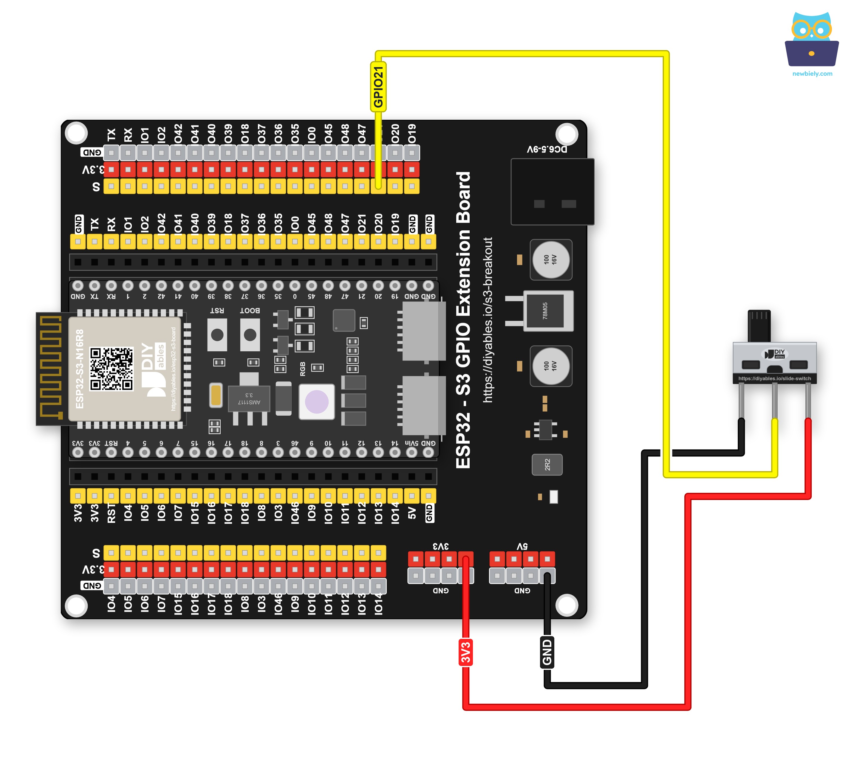
This image is created using Fritzing. Click to enlarge image
Safety Notes
Connect pin 3 to 3V3 only, never to 5V or VIN. Whenever the handle points at pin 3, COM passes that voltage directly to GPIO21, and the ESP32 S3 GPIOs are made for 3.3V only, so 5V can ruin the pin. GPIO21 must also stay in input mode for as long as the switch is attached. Through COM, the pin is always tied to 3V3 or GND; if the code made it an OUTPUT at the opposite level, that would be a short circuit. If you ever move COM to another GPIO, stay away from the strapping pins GPIO0, GPIO3, GPIO45 and GPIO46: a switch that holds one of them at the wrong level during reset can change how the chip starts. GPIO21 has no such job, so the handle can be on either side when you power up or upload.
How To Program For Slide Switch
Since COM drives GPIO21 high or low by itself, setup() only needs pinMode() with plain INPUT, and the internal pull-up stays off. In loop(), digitalRead() returns HIGH when COM touches the 3V3 leg (handle toward pin 3, which the code calls ON) and LOW when it touches the GND leg (handle toward pin 1, called OFF). The contacts chatter briefly as the handle slides, so the sketch keeps the last confirmed level; when a new reading differs, it pauses 50 ms and takes a second reading before it accepts the change.
ESP32 S3 Code - Read the Slide Switch Position
Right after a reset, this sketch prints which side the handle is on. From then on, the Serial Monitor only gets a new line when the handle truly changes sides.
Detailed Instructions
- New to ESP32 S3? Complete our Getting Started with ESP32 S3 guide first.
- Connect the three wires listed in the table above. Make sure pin 3 goes to 3V3, not 5V.
- Plug the ESP32 S3 into your computer with the Type-C cable.
- In the Arduino IDE, choose ESP32S3 Dev Module in Tools > Board and the matching port in Tools > Port.
- Copy the code into a fresh sketch and click Upload.
- Set the Serial Monitor to 9600 baud. Click its clock icon (Toggle Timestamp) to see the time of each line.
- Press the RST button once, so the power-up line is printed while the monitor is open.
- Move the handle across five times, pausing briefly at each end.
- Pro Tip: Look at the timestamps. Each slide should create a single line, bounce or not. If one slide ever prints two lines a few milliseconds apart, raise SETTLE_TIME a little, for example to 80.
Line one is printed by setup(). Each of the other five lines is one slide of the handle.
ESP32 S3 Code - Slide Switch with 2 Wires and INPUT_PULLUP
Want one wire less, or need 3V3 for a sensor? Just remove the pin 3 wire. Inside the ESP32 S3, GPIO21 has its own pull-up resistor. Choosing INPUT_PULLUP in pinMode() turns it on, and it keeps the pin at HIGH while COM is away from GND.
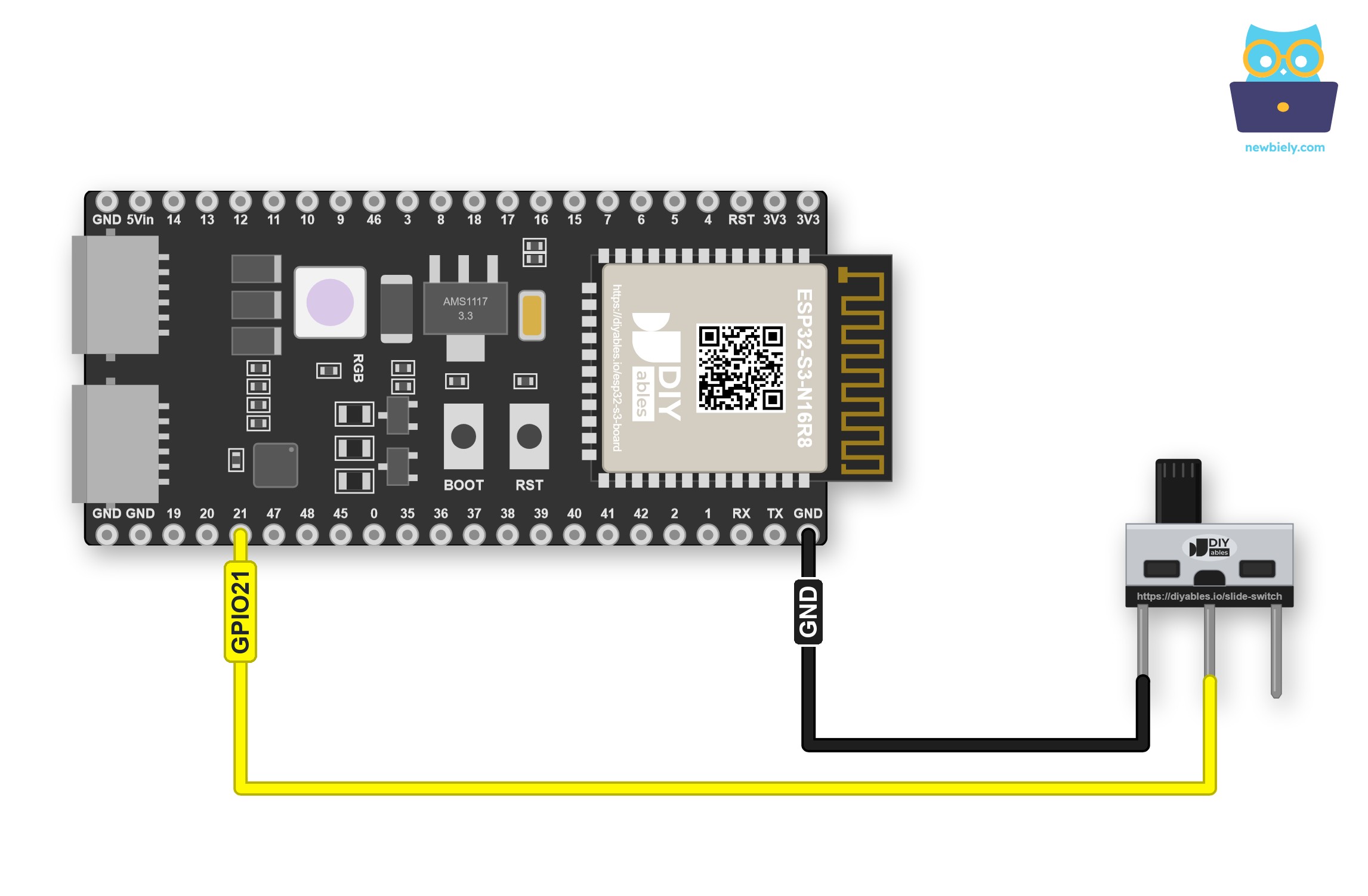
This image is created using Fritzing. Click to enlarge image
| Slide Switch Pin | ESP32 S3 Pin |
|---|---|
| Pin 1 | GND |
| Pin 2 (COM) | GPIO21 |
| Pin 3 | not connected |
This wiring turns the logic around. When the handle sits next to pin 1, COM links GPIO21 to GND, so digitalRead() gives LOW, and the code reports ON. When it sits next to pin 3, COM meets only an unused leg, nothing pulls the pin down, the pull-up wins, and the code reports OFF.
Detailed Instructions
- Unplug the pin 3 wire. Leave the GND and GPIO21 wires in place.
- Upload SlideSwitchInputPullup the usual way.
- Leave the monitor on 9600 baud, press RST, and slide the handle back and forth three times.
- Pro Tip: To keep the ON and OFF labels of the 3-wire circuit, simply swap the two words inside stateName(). The wiring does not need to change.
Either circuit works fine. The 3-wire one is easier to think about, because HIGH means ON. The 2-wire one saves a wire and keeps the 3V3 pin free. Just make sure the sketch matches the wiring.
Application and Project Ideas
A setting you can see and touch is useful in many ESP32 S3 builds.
- Web settings lock: Let a web server on the ESP32 S3 accept new settings only while the switch is ON, so nobody can change them over WiFi without touching the device.
- Battery saver: Read the switch at power-up and go straight into deep sleep when it is OFF.
- Logger pause: Stop writing sensor readings to an SD card while the handle is on the OFF side, so the card can be removed without losing data.
- Two-language display: Show the messages on an LCD in English on one side and in your own language on the other.
- Night mode for an LED strip: Dim the LEDs to a soft glow when the handle is moved to the night side.
Challenge Yourself
- Beginner: Keep a running total of moves since power-up, and add it to each ON or OFF line.
- Intermediate: Add a second slide switch on another free GPIO (not a strapping pin) and print one of four modes, like a two-position DIP switch.
- Advanced: GPIO21 is an RTC pin on the ESP32 S3, so it can wake the chip. Put the board into deep sleep and let a move of the handle wake it up, then print which side it was moved to.
Video Tutorial
Watch the step-by-step video walkthrough for this ESP32 S3 project below.