
ESP32 S3 - BTS7960 Motor Driver
The shoulder is the hardest-working joint of a robot arm. It carries the upper arm, the elbow, the gripper and whatever the gripper holds, so its 12V gear motor can ask for many amps, most of all when the arm is stretched out straight. Small driver boards get hot and give up long before that. The DIYables BTS7960 43A motor driver is made for this kind of load, and in this guide the ESP32 S3 runs it with four GPIO pins: it lifts, holds the speed, stops hard, lowers at half power and then lets go.
What you'll build in this tutorial:
- A clear picture of the BTS7960 board: its 8-pin control header, its four screw terminals and the job of each pin
- A circuit with six jumper wires on GPIO41, GPIO42, GPIO1, GPIO2, 5V and GND, plus a 12V adapter that feeds only the motor
- A sketch without any library that raises the speed step by step, brakes, runs backward at half power and then coasts
- A Serial Monitor log that names each stage, so you can match each line with what the motor shaft does
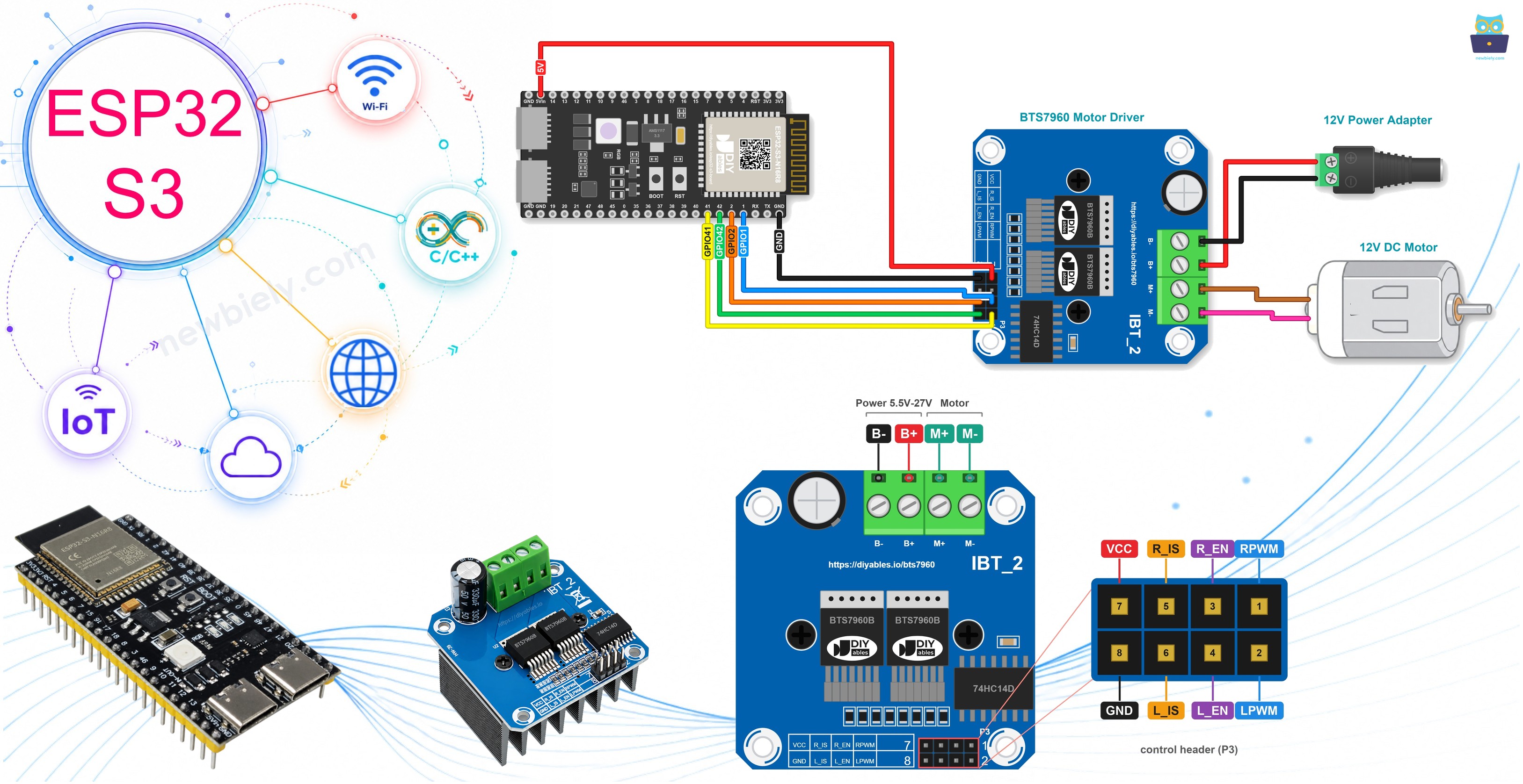
Hardware Preparation
Or you can buy the following kits:
| 1 | × | DIYables ESP32 S3 Starter Kit (ESP32 S3 included) | |
| 1 | × | DIYables Sensor Kit (18 sensors/displays) |
Additionally, some of these links are for products from our own brand, DIYables .
Overview of BTS7960 Motor Driver
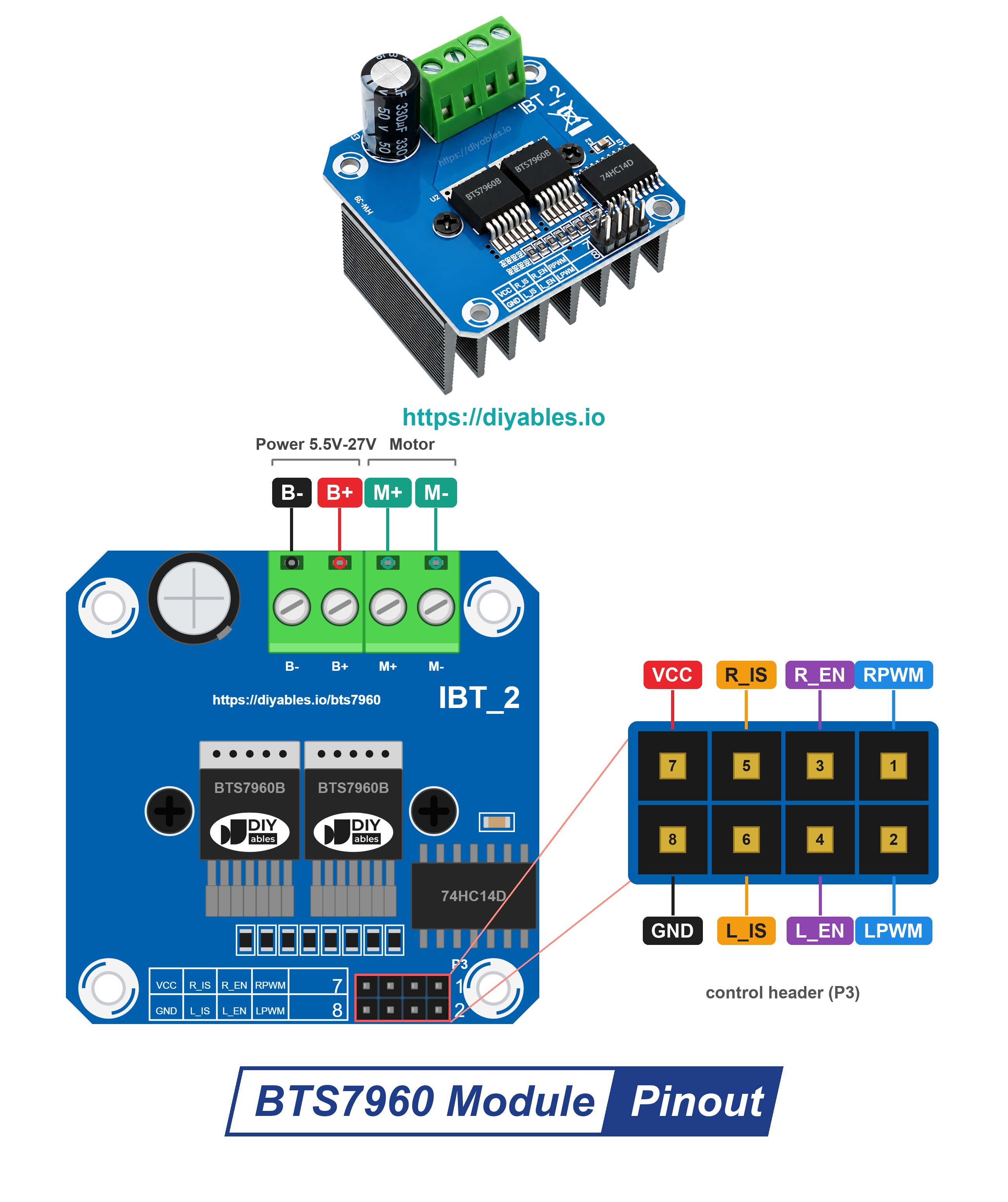
Shops sell this board under several names, such as "IBT-2" or "HW-039", but the design is the same. The power work is done by two Infineon BTS7960B chips on the upper face of the board, and a large heat sink fixed below the PCB keeps them cool. Picture each BTS7960B as a changeover switch on one motor lead: it links that lead with B+ or with B-, never both. That is called a half-bridge. Two half-bridges side by side form a full H-bridge, so the board can send current through one motor either way round. In front of the power chips sits a small 74HC14 chip as a buffer. The ESP32 S3 pins only see this chip, and the big motor current stays on the power side.
Speed control works with PWM. The GPIO pin flips between HIGH and LOW about a thousand times per second. When the pin is HIGH for most of each tiny cycle (a high duty cycle), the motor gets nearly the full 12V and runs fast. When it is HIGH for only a short part, the motor gets less and runs slower.
Key Specifications
Any motor supply from 5.5V to 27V DC works on B+ and B-, which covers 6V, 12V and 24V motors. 43A is the level at which the chips begin current limiting. Treat it as a ceiling, not a target: a motor that turns for a long time should draw far less, because for long runs the cooling is what counts. RPWM and LPWM can take PWM signals up to 25 kHz, and the chips guard themselves with current limiting and over-temperature protection.
| Property | Value |
|---|---|
| Bridge type | 1 full H-bridge made of 2 BTS7960B half-bridge chips |
| Drives | 1 brushed DC motor, turning either way |
| Motor voltage on B+ and B- | 5.5 to 27V DC |
| Current | 43A at most (the chips' current-limit level, not a long-run rating) |
| PWM frequency on RPWM and LPWM | 25 kHz max |
| VCC | feeds the 74HC14 buffer (5V, from the 5V pin on this board) |
| Protection | current limiting, over-temperature |
BTS7960 Pinout
The control header holds eight pins, four per row, and a printed label names each one:
- RPWM — speed signal for the right half; any duty here spins the motor forward (in this guide, the arm rises)
- LPWM — speed signal for the left half; any duty here spins the motor backward (the arm comes down)
- R_EN — HIGH wakes the right half-bridge, LOW turns it off
- L_EN — HIGH wakes the left half-bridge, LOW turns it off
- R_IS / L_IS — current-sense / fault signals (silkscreen: "R_S" and "L_S"); this project gives them no wire
- VCC — feeds just the buffer chip and the power LED; it gives no power to the motor
- GND — ground of the logic side, tied to B- on the module itself
Four screw terminals take the thick wires:
- B+ — supply plus, from the 12V adapter
- B- — supply minus
- M+ / M- — one motor wire each
How the Pins Move the Motor
When both enable pins are HIGH, this is what the PWM pair does:
| RPWM | LPWM | Motor reaction |
|---|---|---|
| duty 1-255 | 0 | spins forward; the speed follows the duty |
| 0 | duty 1-255 | spins backward; the speed follows the duty |
| 0 | 0 | brakes; M+ and M- get shorted together, so the shaft stops in a moment |
Now pull both enable pins LOW. With the driver switched off, no power pushes the motor and no brake holds it. It coasts, and only friction slows it down. On an arm joint you will notice the difference. The brake halts the shoulder quickly, while a coasting motor gives almost no resistance, so a heavy arm may slowly drop under its own weight. One rule holds in every case: RPWM or LPWM, one of the two must always sit at 0. Driving both together is never allowed.
Logic Power and Common Ground
The VCC wire of this board comes from the 5V pin of the ESP32 S3. On the module, this wire reaches just the small 74HC14 buffer chip. The maker's guide puts that supply at 5V. The four control inputs work with anything from 3.3V to 5V, so they take the GPIO signals of the ESP32 S3 as they are. Each of these inputs has a pull-down resistor, and the sense pins have no wire, so no 5V comes back into a GPIO. Ground needs just one jumper. On the module, the GND header pin and B- are already linked, so connecting GND of the ESP32 S3 to GND of the header also puts the ESP32 S3 on the ground of the adapter. B+ is a different story: keep its 12V far away from every ESP32 S3 pin.
Many beginners know the L298N. It has two channels of about 2A each and drops around 2V on the way to the motors. The BTS7960 has only one channel, but it carries far more current and wastes almost no voltage. If your motor is small, go to ESP32 S3 - DRV8833 DC Motor Driver instead.
Wiring Diagram
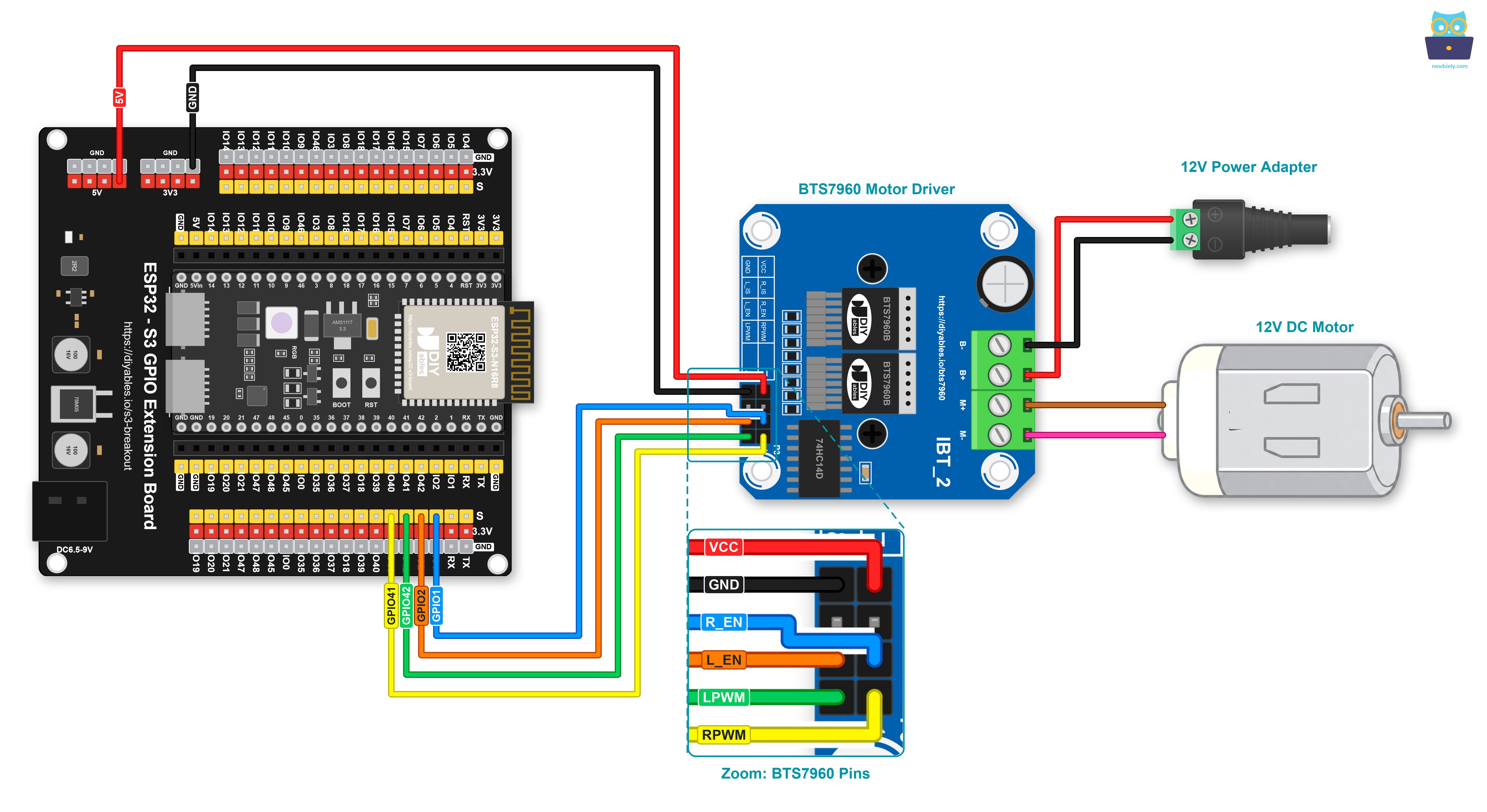
On the ESP32 S3, the four control wires start from one header, where GPIO1, GPIO2, GPIO42 and GPIO41 are neighbors near a GND pin, while the 5V wire starts from the header across from it. These four GPIOs have no strapping, USB, serial or PSRAM role, and the heavy side is just as simple, because the motor and the 12V adapter end up in the four screw terminals of the module.
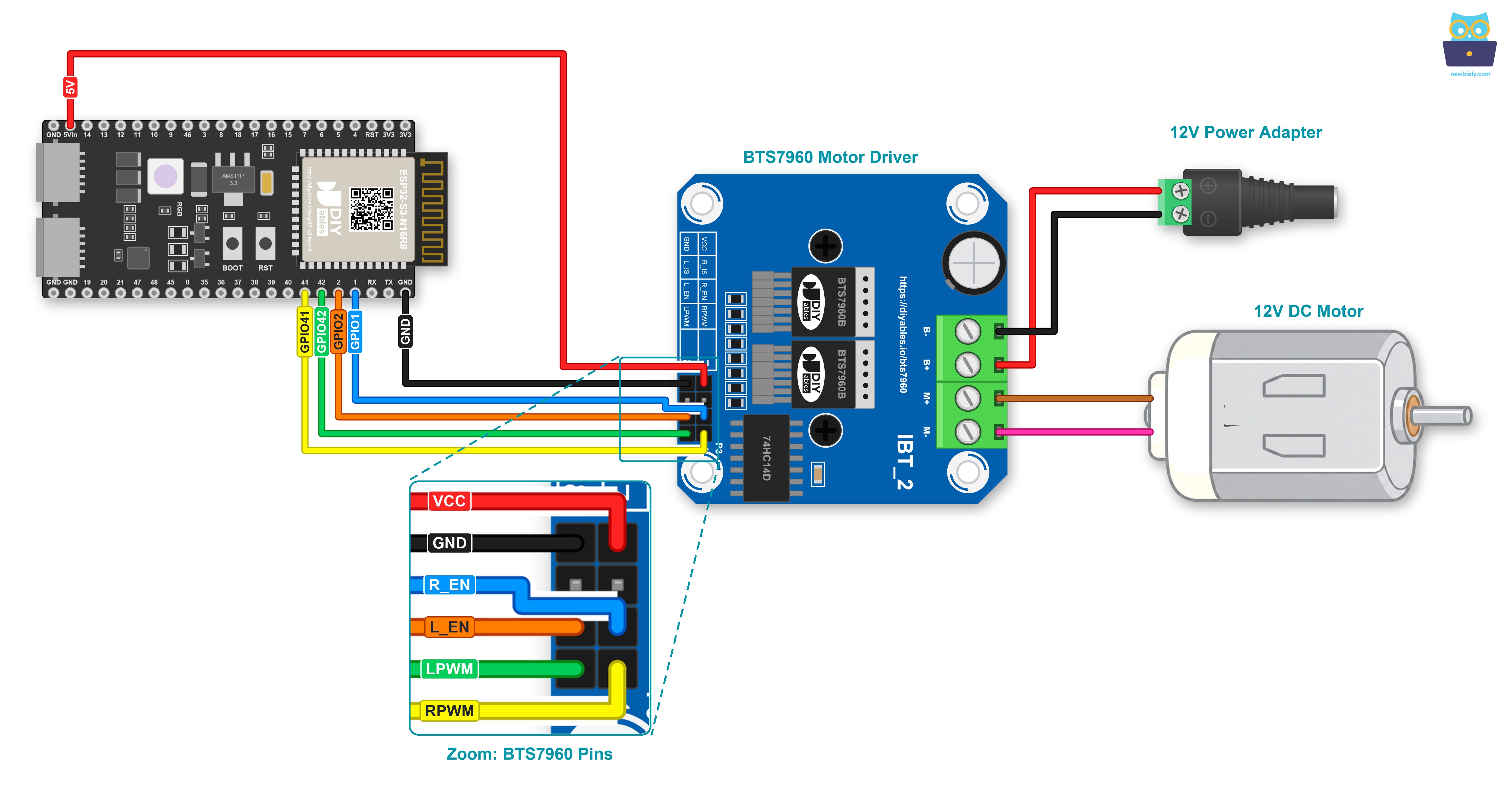
This image is created using Fritzing. Click to enlarge image
| Pin on the BTS7960 | Where the wire goes |
|---|---|
| RPWM | GPIO41 |
| LPWM | GPIO42 |
| R_EN | GPIO1 |
| L_EN | GPIO2 |
| VCC | 5V |
| GND | GND |
| B+ | DC power jack +, from the 12V adapter |
| B- | DC power jack -, from the 12V adapter |
| M+ and M- | gear motor, one lead each |
| R_IS and L_IS | left open |
If you plan to keep this circuit, think about screw terminals. In this case, use a Screw Terminal Block for ESP32 S3. The ESP32 S3 plugs into it, and each pin gets a screw terminal. This is how it looks with the screw terminal board:
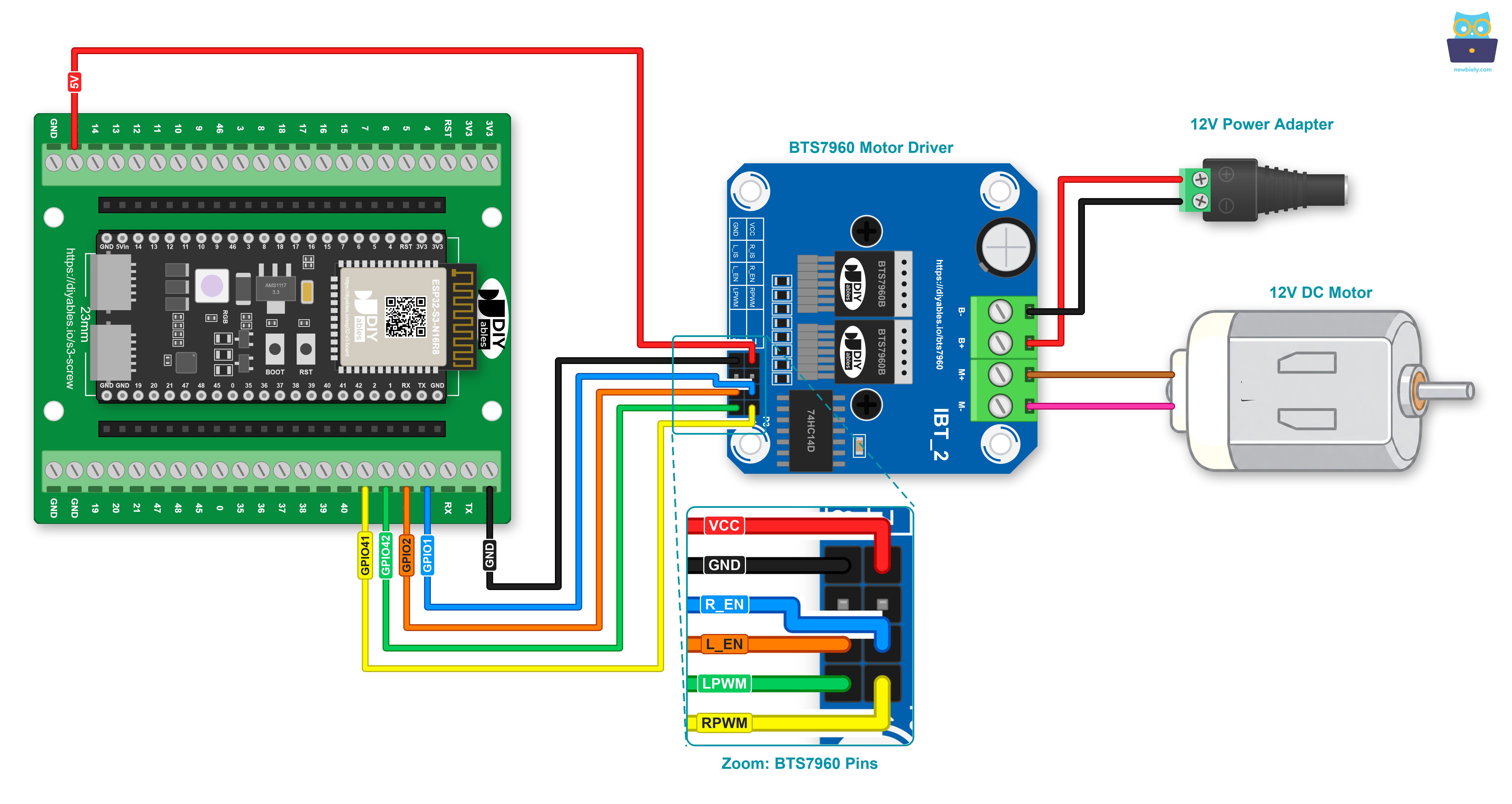
This image is created using Fritzing. Click to enlarge image
Or plug the ESP32 S3 into a GPIO Breakout Board for ESP32 S3. The same wiring then looks like this:
This image is created using Fritzing. Click to enlarge image
Safety Notes
The 12V adapter goes into the socket only after the rest of the circuit is finished. Before that, find the + and - marks on the DC power jack and make sure they meet B+ and B-, because swapping them can harm the module. The adapter should be able to give more current than your motor draws. A gear motor draws the most at start-up and whenever its shaft is held still, and on an arm joint that happens each time the arm runs into the end of its travel. So run the first test with the motor loose on the desk and nothing fixed to the shaft, and build it into the arm only when it works. Route the B+ wire away from the ESP32 S3 headers, since 12V on a GPIO destroys it at once. Finally, 43A is a peak limit and not a working current: a heat sink that gets hot during a long run means the load is too heavy for this setup.
How To Program For BTS7960 Motor Driver
Nothing from the Library Manager is needed. The Arduino core for ESP32 already has both functions the sketch uses: analogWrite() sends a duty from 0 to 255 to RPWM or LPWM, and digitalWrite() sets R_EN and L_EN. Each motor state has its own helper: runForward(), runReverse(), brakeMotor() and coastMotor(). A run helper first writes 0 to the other PWM pin and only then puts a duty on its own pin, so forward and reverse can never be active together. setup() also writes 0 to both PWM pins before it raises the enables, so the motor does not twitch at start-up.
ESP32 S3 Code - BTS7960 Motor Driver
One pass of the loop takes about nine seconds and then repeats: speed up, hold, slow down, brake, lower at half power, coast.
Detailed Instructions
- New to ESP32 S3? Complete our Getting Started with ESP32 S3 guide first.
- Wire everything, 12V unplugged: Connect the six signal wires from the table, screw the motor leads into M+ and M-, and run the two DC power jack wires to B+ and B-. The 12V adapter stays out of the socket.
- Connect to the PC: Use the Type-C cable to link the ESP32 S3 to your computer.
- Set up the IDE: Open the Arduino IDE, then pick ESP32S3 Dev Module and the right COM port from the Tools menu.
- Upload: Paste the code into an empty sketch and click Upload. The motor stays still for now, because it has no power yet.
- Give the motor power: Now plug in the 12V adapter.
- Open the log: Bring up the Serial Monitor, set the speed to 9600, and switch on its clock icon so every line gets a time.
- Watch the shaft: It speeds up one way, runs fast, slows down, stops sharply, turns the other way at about half speed, and at last rolls to a stop by itself.
- Pro Tip: Does "Raise" move the arm down instead of up? Don't touch the code. First switch off the 12V power, then exchange the leads in the M+ and M- terminals.
The times show the code at work: about one second for each ramp, two seconds at full speed, one second of brake, two seconds of reverse and two of coasting. Now watch the motor at the two stop lines. At "Halt" the shaft stands still almost at once. At "Relax" it runs on for a short while and slows down by itself. Do you hear a faint whine while the shaft turns slowly? That is fine. The PWM from analogWrite() runs at about 1 kHz, a sound your ear can pick up from the motor coils.
Application and Project Ideas
With an ESP32 S3 in front of a 43A H-bridge, heavy moving builds are within reach.
- Full robot arm: Give each heavy joint, such as the shoulder and the elbow, its own BTS7960, and use a smaller driver for the light wrist.
- Chicken coop door: Lift the door with a 12V gear motor at sunrise and close it at dusk, with a light sensor as the clock.
- Solar panel tilt: Turn a 12V linear actuator a little each hour, so the panel faces the sun.
- TV lift cabinet: Raise a TV out of a cabinet and lower it again from a web page served by the ESP32 S3.
- Pottery wheel: Set the speed of a strong 12V or 24V motor with a potentiometer and change the direction with a switch.
Challenge Yourself
- Beginner: Change HALF_DUTY to 64 and then to 200, and see how the speed of the reverse run changes.
- Intermediate: Add an UP button and a DOWN button. While you hold one, the motor turns that way; when you let go, the motor brakes.
- Advanced: Fix a potentiometer to the shoulder axle, read it on GPIO4 (an ADC1 pin), and stop the arm at an angle you type into the Serial Monitor.
Video Tutorial
A video of this motor test is planned for this spot.