
ESP8266 - 10 Segment LED Bar Graph
Or you can buy the following kits:
| 1 | × | DIYables Sensor Kit (18 sensors/displays) |
Additionally, some of these links are for products from our own brand, DIYables .
This tutorial instructs you how to use ESP8266 NodeMCU to control the 10 Segment LED Bar Graph display. In detail, we will learn:
- How to connect the ESP8266 NodeMCU to the 10 Segment LED Bar Graph
- How to program the ESP8266 NodeMCU to drive the LED bar animation
Overview of 10 Segment LED Bar Graph
| 10 Segment LED Bar Graph | |
|---|---|
| Number of Segments | 10 |
| LED Color | Bright red |
| Forward Voltage | ~2V per segment |
| Forward Current | 20mA max per segment |
| Resistor Required | 220Ω per segment |
The 10 Segment LED Bar Graph Pinout
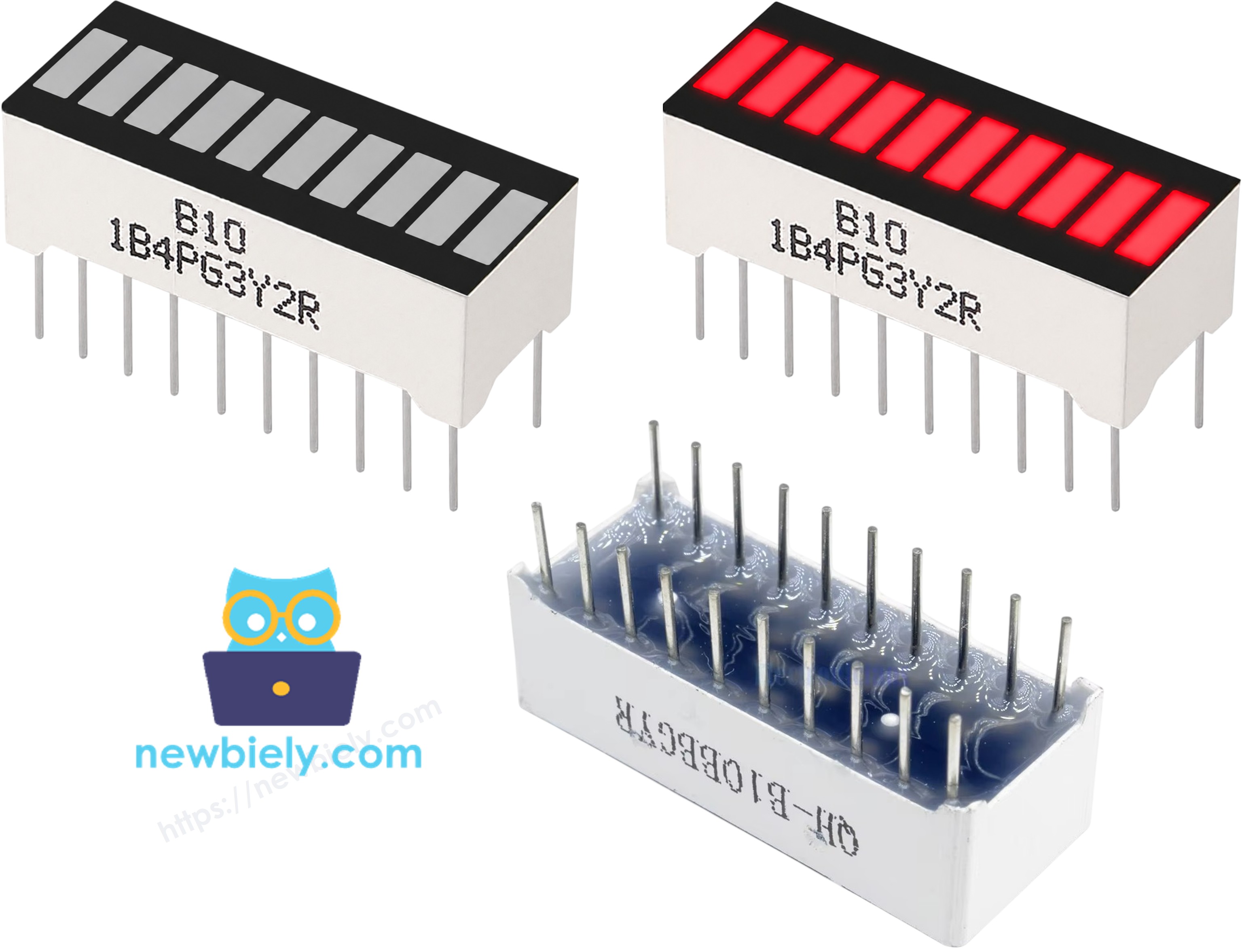
- Anode pins (A1–A10): must be connected to GPIO pins via 220Ω resistors
- Cathode pins (K1–K10): must be connected to GND
※ NOTE THAT:
The ESP8266 NodeMCU operates at 3.3V logic levels. GPIO0 (D3), GPIO2 (D4), and GPIO15 (D8) are boot strapping pins — they affect the ESP8266 boot mode if held HIGH or LOW at power-up. Once the board has booted, they function as normal GPIO outputs. If you experience boot issues, verify these pins are not accidentally held to the wrong level at startup.
Wiring Diagram
Connect the LED bar graph to the ESP8266 NodeMCU as shown in the table below.
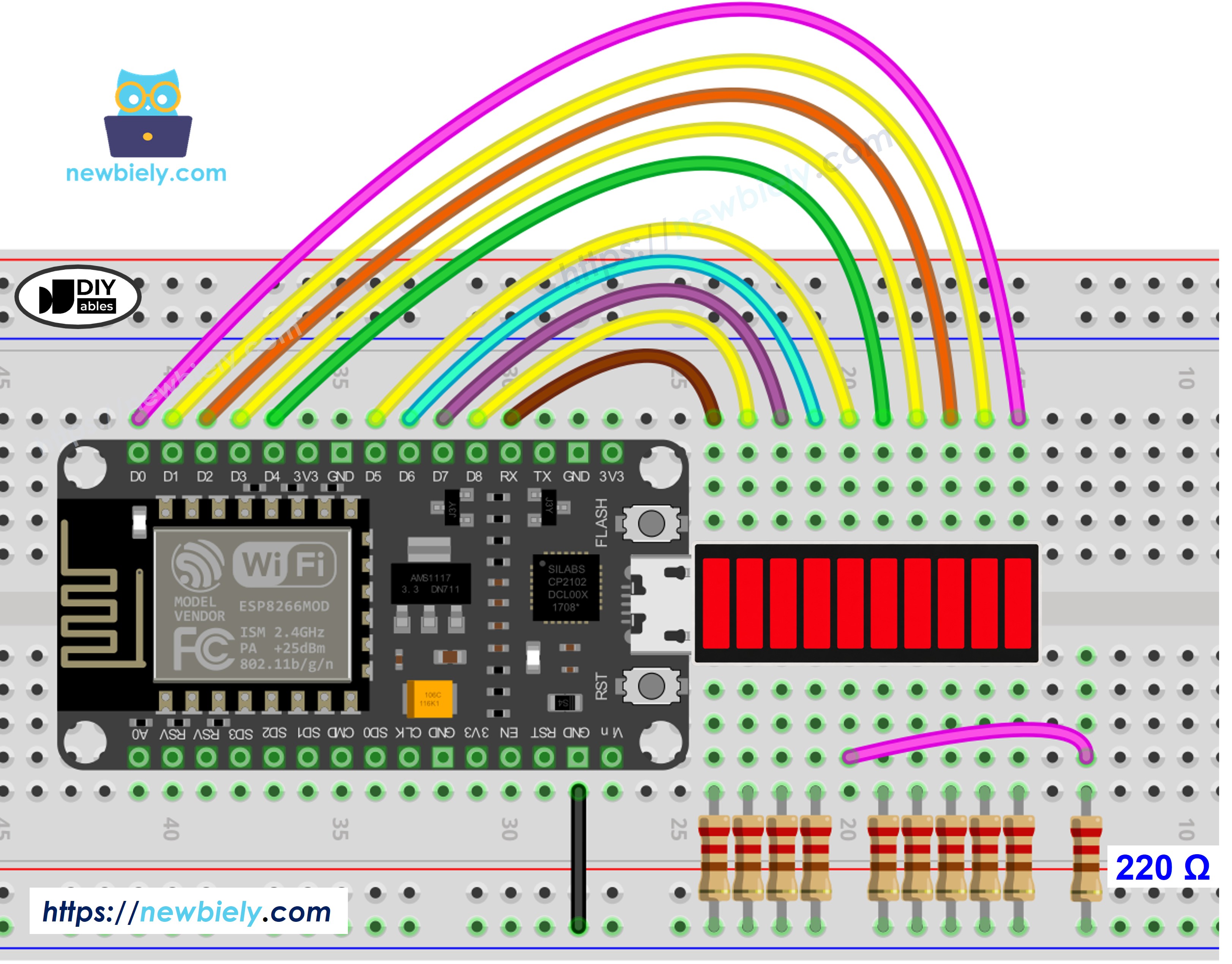
This image is created using Fritzing. Click to enlarge image
See more in ESP8266's pinout and how to supply power to the ESP8266 and other components.
| LED Bar Graph | ESP8266 NodeMCU Pin |
|---|---|
| A1 (Anode 1) | D0 / GPIO16 (via 220Ω) |
| A2 (Anode 2) | D1 / GPIO5 (via 220Ω) |
| A3 (Anode 3) | D2 / GPIO4 (via 220Ω) |
| A4 (Anode 4) | D3 / GPIO0 (via 220Ω) |
| A5 (Anode 5) | D4 / GPIO2 (via 220Ω) |
| A6 (Anode 6) | D5 / GPIO14 (via 220Ω) |
| A7 (Anode 7) | D6 / GPIO12 (via 220Ω) |
| A8 (Anode 8) | D7 / GPIO13 (via 220Ω) |
| A9 (Anode 9) | D8 / GPIO15 (via 220Ω) |
| A10 (Anode 10) | D9 / GPIO3 / RX (via 220Ω) |
| K1–K10 (Cathodes) | GND |
How To Program ESP8266 NodeMCU for 10 Segment LED Bar Graph
- The first step is to define the array of GPIO pin numbers connected to the LED bar graph anodes
- Each pin must be configured as an output using pinMode()
- To illuminate a segment, set the corresponding GPIO pin HIGH using digitalWrite()
- To turn off a segment, set the pin LOW
- No external library is required for this project
ESP8266 NodeMCU Code for 10 Segment LED Bar Graph
Detailed Instructions
- If this is the first time you use ESP8266, see how to set up the environment for ESP8266 in Arduino IDE.
- Wire the components as shown in the diagram.
- Connect the ESP8266 NodeMCU board to your computer using a USB cable.
- Open Arduino IDE on your computer.
- Select the correct board and port under Tools → Board and Tools → Port.
- Copy the code above and paste it into the Arduino IDE.
- Click Upload to compile and upload the code to the ESP8266 NodeMCU.
- Open the Serial Monitor (baud rate: 115200) to observe the output.
Serial Monitor Output
Additional Knowledge
The ESP8266 exposes only approximately 11 usable GPIO pins, which is a significant constraint compared to the ESP32's 30+ available GPIOs. Several of those 11 pins carry boot-mode sensitivity (GPIO0, GPIO2, GPIO15), meaning the logic level present on those pins at power-up determines how the chip starts. This limits the number of output-heavy projects that can be implemented directly on the ESP8266 without peripheral assistance.
When more output channels are required than the ESP8266 can provide natively, a shift register such as the 74HC595 is a practical solution. A single 74HC595 delivers 8 output lines while consuming only 3 GPIO pins (data, clock, latch). Multiple 74HC595 chips can be daisy-chained to expand output capacity further without adding GPIO usage, making them well suited for driving LED arrays, bar graphs, or segment displays on pin-constrained platforms.