
ESP8266 - SW-420 Vibration Sensor
The SW-420 vibration sensor module reacts to shaking, knocking, or shock in whatever it is mounted on. It suits projects such as a simple burglar or tamper alarm, a package that reports rough handling, or a machine that needs a warning when it starts shaking abnormally.
This tutorial instructs you how to use the ESP8266 and a SW-420 vibration sensor to detect vibration. We will explore:
- How to connect the SW-420 vibration sensor to the ESP8266
- How to program the ESP8266 to detect vibration using the SW-420 vibration sensor.
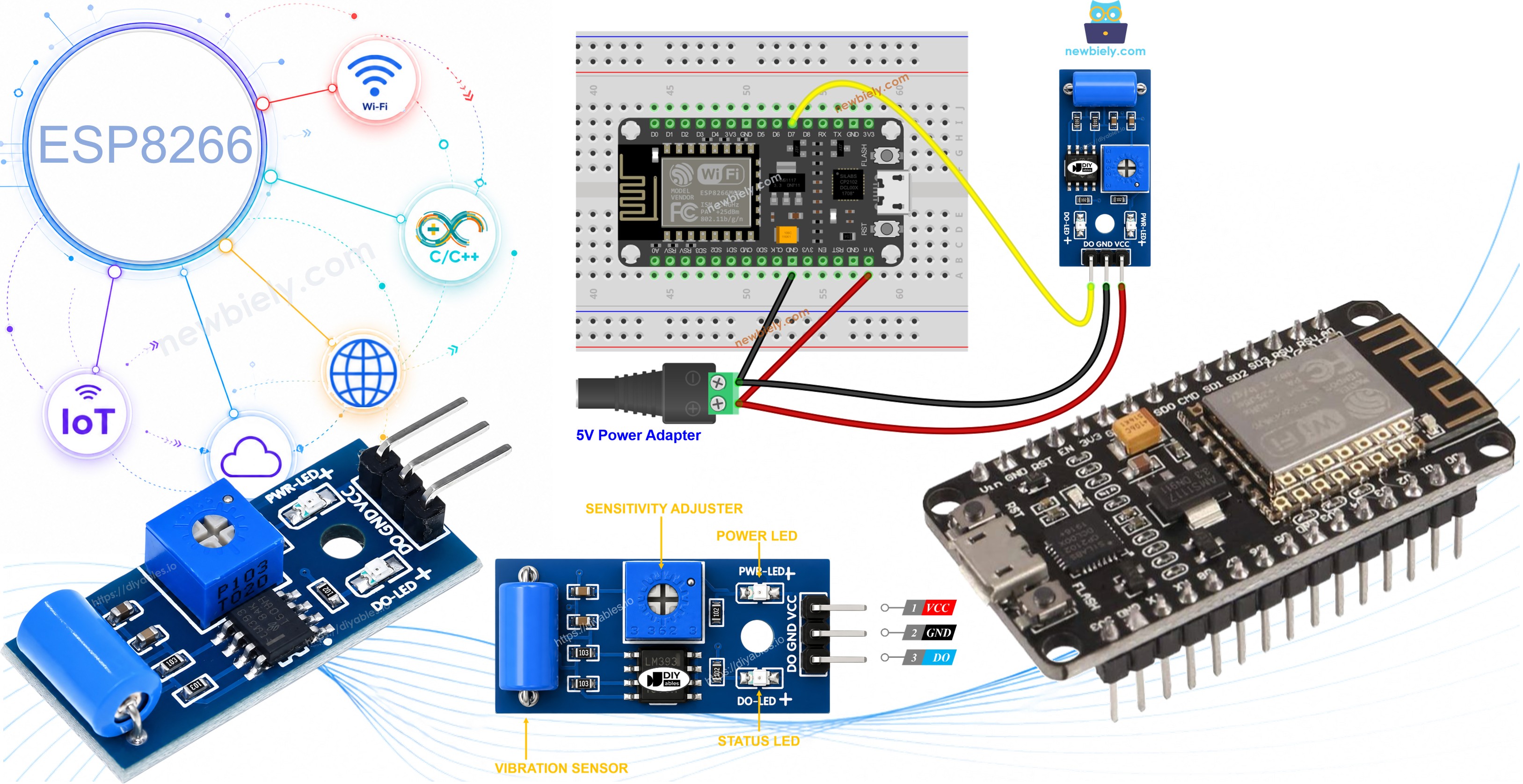
From there, the code can easily be extended to sound a buzzer, flash an LED, or send a notification whenever vibration is picked up.
Hardware Preparation
Or you can buy the following kits:
| 1 | × | DIYables Sensor Kit (18 sensors/displays) |
Additionally, some of these links are for products from our own brand, DIYables .
Overview of SW-420 Vibration Sensor
The SW-420 vibration sensor module is built to pick up shaking, knocking, or shock affecting whatever it is mounted on. Inside its metal case sits a small spring-based switch positioned close to a metal contact; an onboard LM393 comparator watches that switch and turns any disturbance into a clean digital signal, while a small onboard potentiometer lets you dial in how much shaking is needed before it trips.
The SW-420 Vibration Sensor Pinout
The SW-420 vibration sensor has three pins:
- VCC pin: needs to be connected to VCC (3.3V to 5V)
- GND pin: needs to be connected to GND (0V)
- DO pin: is an output pin: LOW while everything is still and HIGH the moment vibration or shock is detected. This pin needs to be connected to ESP8266's input pin.
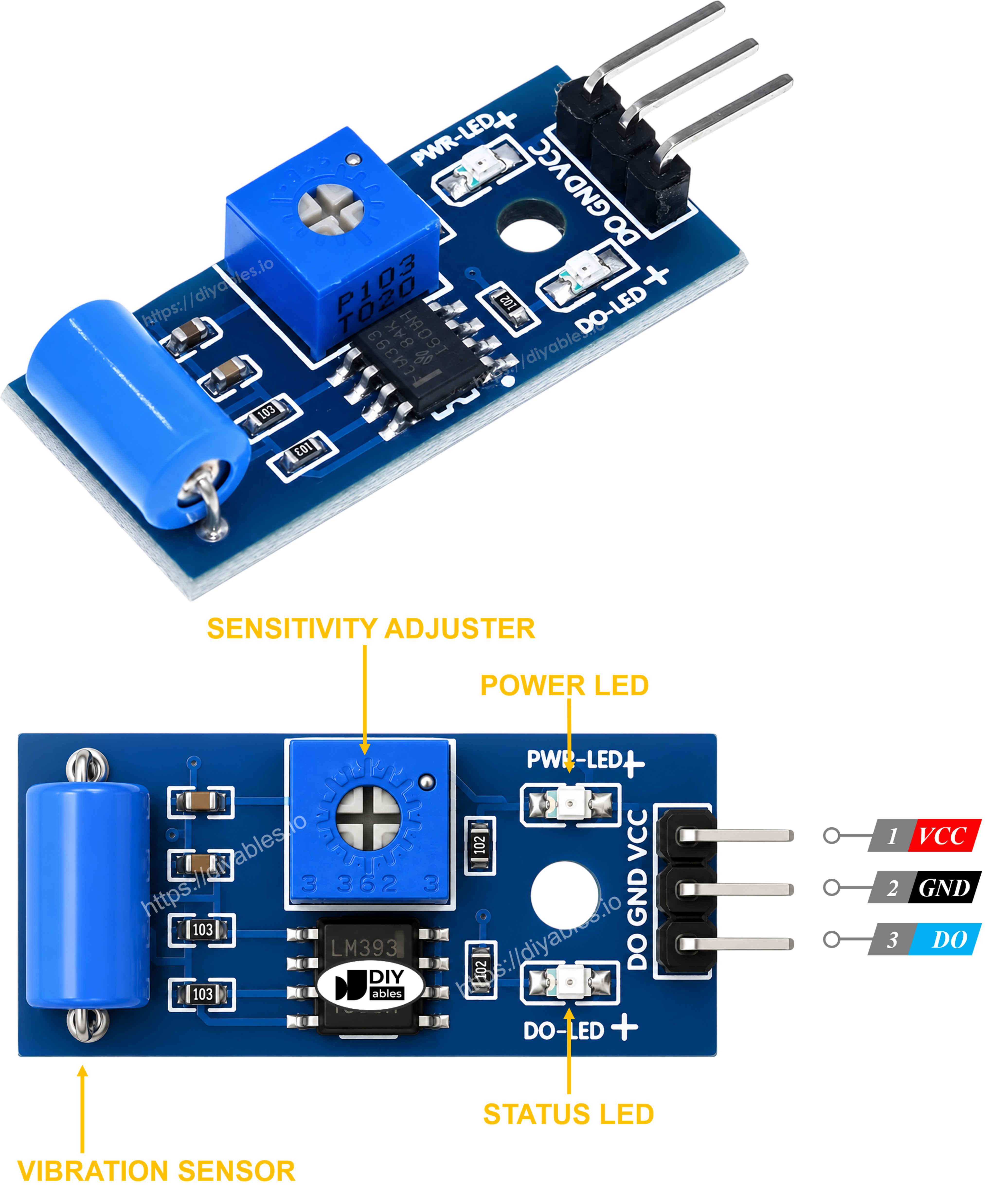
The SW-420 vibration sensor module comes with two LED indicators:
- One LED indicates the power status.
- Another LED lights up whenever the DO pin goes HIGH, i.e. whenever vibration is detected.
How It Works
Here's how the sensor behaves:
- While the module sits still, the internal spring switch stays open and the DO pin stays LOW.
- The instant the module is shaken, knocked, or bumped, the spring switch touches the contact and the LM393 comparator drives the DO pin HIGH.
- Turning the onboard potentiometer clockwise or counterclockwise raises or lowers how strong a shock must be before the output switches.
Wiring Diagram
- The wiring diagram between ESP8266 and SW-420 vibration sensor
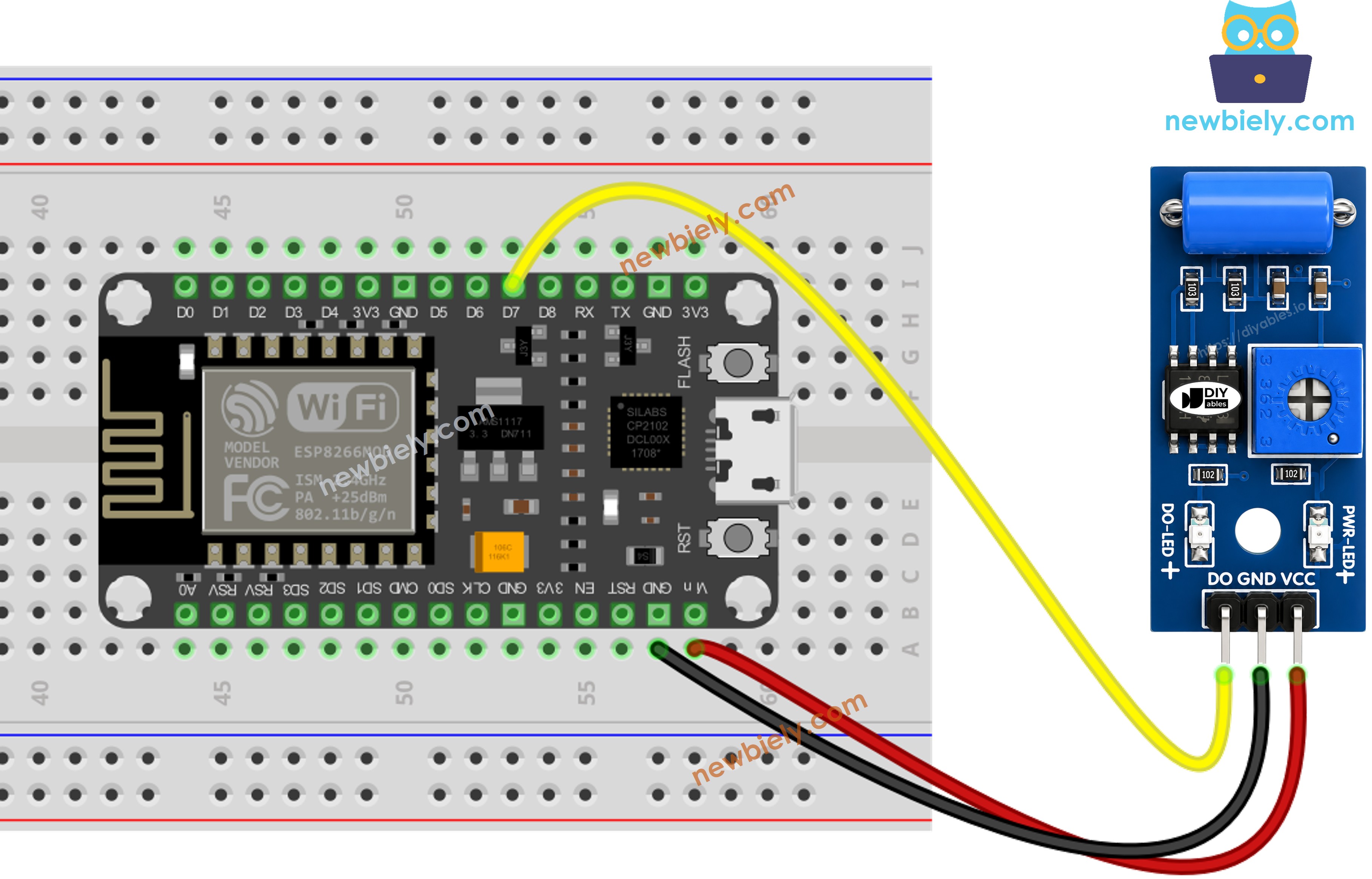
This image is created using Fritzing. Click to enlarge image
See more in ESP8266's pinout and how to supply power to the ESP8266 and other components.
How To Program For SW-420 Vibration Sensor
- Initializes the ESP8266 pin to the digital input mode by using pinMode() function. For example, pin D7
- Reads the state of the ESP8266 pin by using digitalRead() function.
ESP8266 Code - Detecting the vibration
Detailed Instructions
To get started with ESP8266 on Arduino IDE, follow these steps:
- Check out the how to setup environment for ESP8266 on Arduino IDE tutorial if this is your first time using ESP8266.
- Wire the components as shown in the diagram.
- Connect the ESP8266 board to your computer using a USB cable.
- Open Arduino IDE on your computer.
- Choose the correct ESP8266 board (e.g. NodeMCU 1.0 (ESP-12E Module)), and its respective COM port.
- Copy the above code and open with Arduino IDE
- Click Upload button on Arduino IDE to upload code to ESP8266
- Tap or shake the SW-420 sensor
- Check out the result on the Serial Monitor.
From here, the sketch can be extended so the ESP8266 sounds a buzzer, lights an LED, or pushes a notification whenever vibration is picked up. For detailed instructions and additional information, please refer to the tutorials provided at the end of this guide.
Troubleshooting
If you encounter issues with the SW-420 vibration sensor not functioning correctly, try the following troubleshooting steps:
- Adjust the sensitivity: Turn the onboard potentiometer to make the sensor more or less sensitive if it triggers too easily or not at all.
- Isolate it from ambient vibration: Mount the module away from motors, fans, or other sources of constant background vibration that could cause false triggers.
- Check the wiring: Make sure the VCC, GND, and DO pins are connected correctly.
- Check the power supply: Ensure that the power supply is clean and stable for consistent readings.